
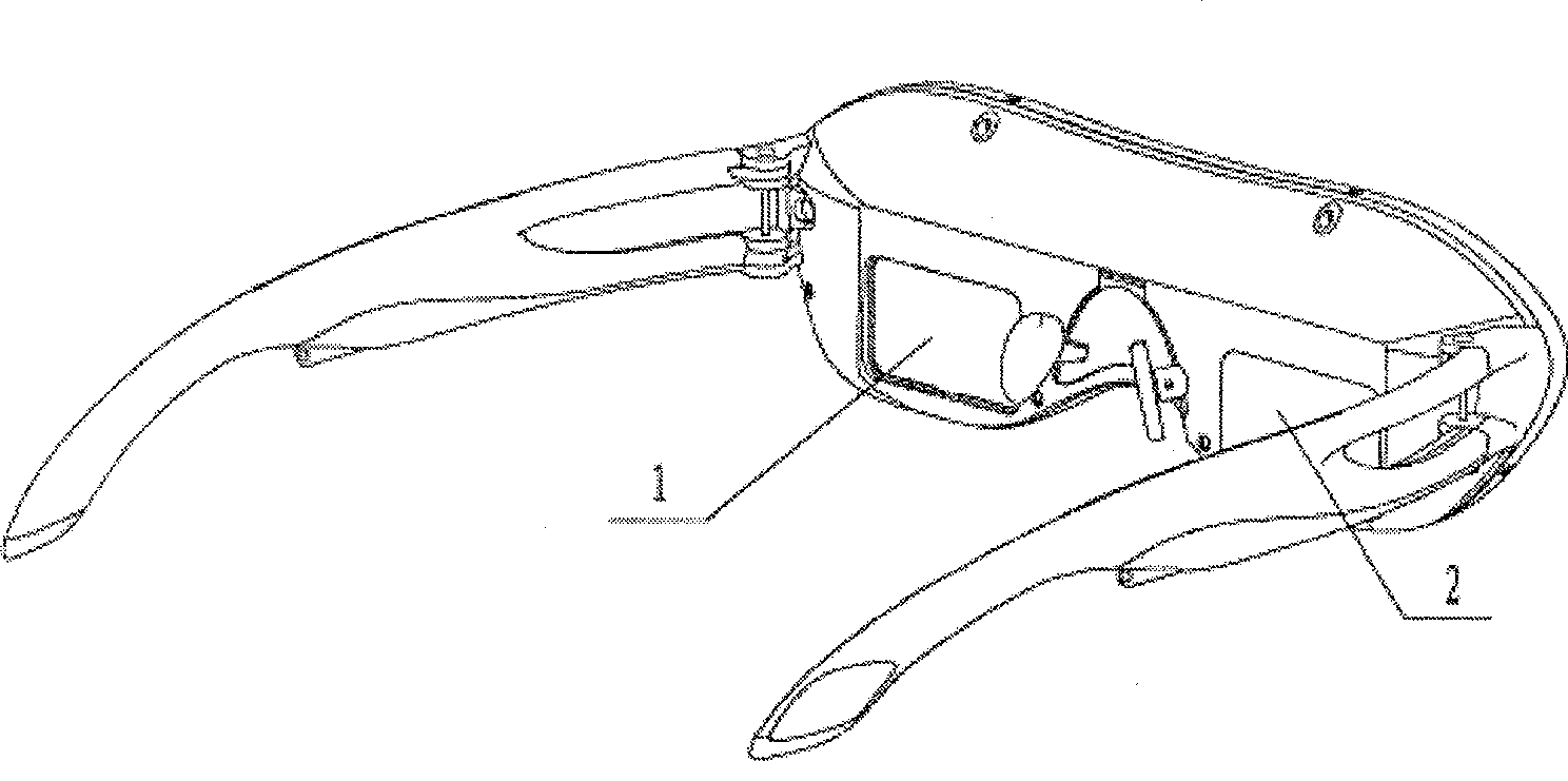
Freely curved face total reflection type visual optical edge glass

A total reflection, optical technology, applied in the direction of optics, prisms, optical components, etc., can solve the problems of undesigned parallelism adjustment mechanism, effect of affecting observation, chromatic aberration, large distortion, etc., to achieve simple adjustment, easy observation, weight reduction effect

Inactive Publication Date: 2009-05-06
中山市美景光学有限公司
View PDF5 Cites 0 Cited by
  • Summary
  • Abstract
  • Description
  • Claims
  • Application Information

AI Technical Summary

Problems solved by technology

The main disadvantages of this optical system are as follows: 1) Poor imaging quality, mainly due to the long path of light, large loss of light energy, large chromatic aberration, and large distortion; 2) Many optical parts and long processing procedures, especially semi-transparent and semi-transparent The reflector is coated with a layer of semi-transparent and semi-reflective film, which is technically difficult, low in production efficiency, high in waste, high in cost, and poor in economic benefits; On the head of the patient, the pressure on the nose will be high, and it will easily cause fatigue
[0003] In addition, the parallelism of the exit optical axes of the left and right visual optical systems of the current similar glasses displays is guaranteed by the structural size, and no parallelism adjustment mechanism is designed. Therefore, in product assembly, the output of the left and right visual optical systems The parallelism of the incident light axis is difficult to guarantee, which directly affects the observation effect

Method used


Image

  • Freely curved face total reflection type visual optical edge glass
  • Freely curved face total reflection type visual optical edge glass
  • Freely curved face total reflection type visual optical edge glass

Examples


Embodiment Construction

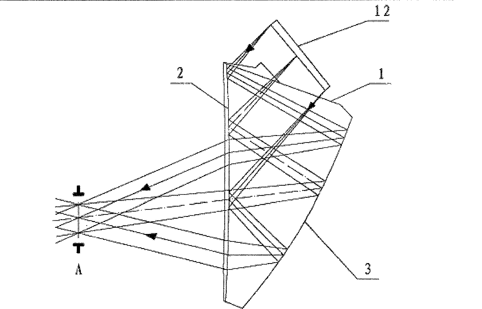
[0023] like image 3 , Figure 4 , shown in Fig. 5, Fig. 6, the visual optical prism of free-form surface total reflection formula of the present invention comprises incident surface 1, exit surface 2, reflecting surface 3, plane-4 and plane two 5, plane-4 and plane two 5 parallel to each other. During use, the microdisplay chip 12 in the glasses display and the incident surface 1 of the visual optical prism are designed with an oblique angle. The related size parameters and the characteristic parameters of the reflective surface 3 form a special optical structure system capable of enlarging the image and correcting various aberrations (such as chromatic aberration, distortion, etc.) of the system. The light of the image displayed by the display chip 12 passes through the incident surface 1 and is totally reflected on the surface of the exit surface 2 to the reflective surface 3, reflected by the reflective surface 3 and refracted to the pupil A through the exit surface 2 to...


PUM

PropertyMeasurementUnit
refractive indexaaaaaaaaaa

Abstract

A kind of guiding mechanism of free curved surface total reflection visual optical prism and outgoing optical axis depth of parallelism, the visual optical prism includes a flat incident plane and sphere outgoing plane and free curved surface reflection plane, the incident plane makes light beam incident into the visual optical prism; the outgoing plane reflects light beam to the reflection plane; the reflection plane reflects light beam back to the outgoing plane, at last the light beam is refracted by the outgoing plane to pupil, the amplified image of the visual optical prism can be seen from pupil, the guiding mechanism includes rack, adjusting screw, two bosses on top of the visual optical prism, and rotation shaft of bass, the visual optical prism is mounted from lower part of the rack, the adjusting screw is screwed in the rack and pressed the visual optical prism. The loss of optical energy is little, quality of imaging is clear, weight is light and convenient to wear, number of optic accessory is little, shape of structure is simple for assembly, and adjustment is easy.

Description

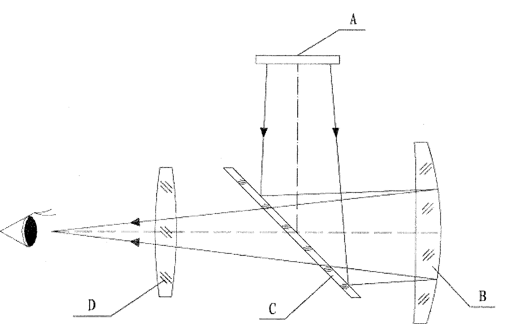
1. Technical field: [0001] The invention relates to a visual optical prism of free-form surface total reflection type. 2. Background technology: [0002] At present, a relatively standard optical system is widely used in eyeglass displays and similar products. like figure 2 Shown, the standard optical system consists of the following optical components: convex lens D, concave mirror B and half mirror C. Its working principle is: the light of the image displayed by the display chip A is first irradiated on the semi-transparent mirror C, and then turned 90° to the concave mirror B coated with a reflective film, and the light is reflected back and passes through the semi-transparent mirror. Half mirror C and convex lens D to the observer's eyes. The main disadvantages of this optical system are as follows: 1) Poor imaging quality, mainly due to the long path of light, large loss of light energy, large chromatic aberration, and large distortion; 2) Many optical parts and long...

Claims


Application Information

Patent Timeline
Patent Type & Authority Patents(China)
IPC IPC(8): G02B27/01G02B5/04G02B1/04G02B1/10G02B7/18
Inventor 贾怀昌
Owner 中山市美景光学有限公司
Learn More