Light modulator

A dimming device and variable technology, applied in lighting devices, light sources, electric light sources, etc., can solve the problems of destroying electronic components or circuits, not getting a sense of snapping, and not being able to lengthen through holes, etc., to prevent temperature rise, The effect of ensuring the snap feeling and improving the static resistance

Active Publication Date: 2009-05-06
MATSUSHITA ELECTRIC WORKS LTD
View PDF9 Cites 0 Cited by
  • Summary
  • Abstract
  • Description
  • Claims
  • Application Information

AI Technical Summary

Problems solved by technology

[0012] Therefore, the shortest distance of creeping discharge between the vicinity of the through hole 103a of the cover 103, which tends to generate static electricity when the operation knob 108 is operated, and the circuit board portion 107 in the body 104 is shortened, thereby causing static electricity to occur when the operation knob 108 is operated. The static electricity in the device body 104 is discharged to the circuit board part 107, causing damage to electronic components or circuits, or the heat generated on the circuit board part 107 is transmitted to the operation knob 108, and the operation knob 108 has a problem of heat.
[0013] By narrowing the through hole 103a and prolonging the shortest distance of creeping discharge, the above-mentioned problems can be solved, but the through hole 103a, as mentioned above, must be capable of penetrating operation since the actuator 106a of the switch 106 is pressed by the pressing piece of the operating knob 108. The size of the knob 108 is formed, so the more the above-mentioned problems are solved, the more the through-hole 103a cannot be lengthened.
[0014] In addition, if the operation knob 108 is arranged on the front of the cover 103, and the parts for the actuator 106a of the push switch 106 are reset, since the through hole 103a can be reduced, the above-mentioned problem can be solved. The concave part 109 and the engaging protrusion 103b cannot be snapped off, so there is no click feeling during operation. In order to obtain the click feeling, the number of parts needs to be increased

Method used


Image

  • Light modulator
  • Light modulator
  • Light modulator

Examples


Embodiment Construction

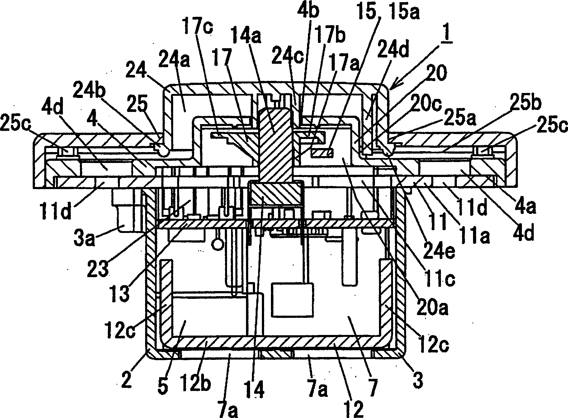
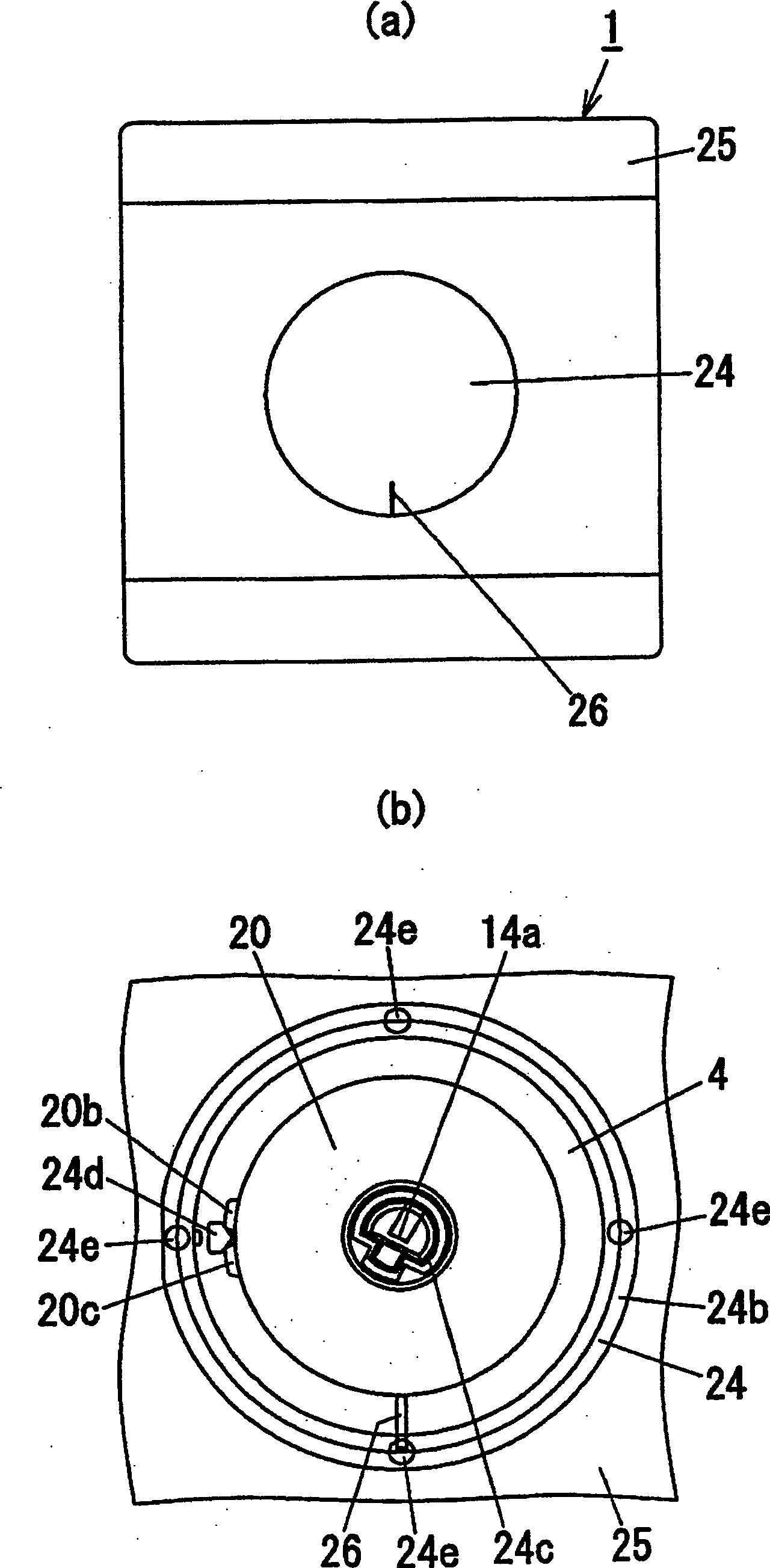
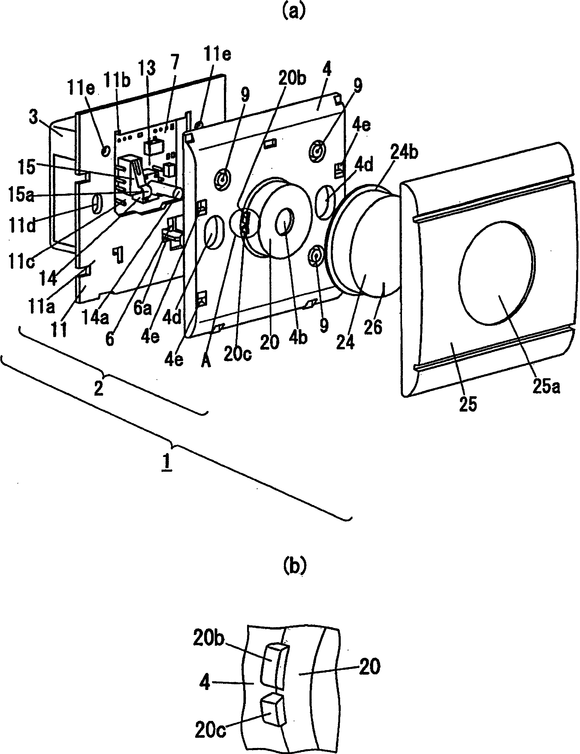
[0026] Below, refer to Figure 1 to Figure 5 The lighting device 1 of the present invention will be described. In addition, in figure 1 Among them, the front direction is the upper side of the dimming device 1, the left direction is the right side of the dimming device 1, the right direction is the left side of the dimming device 1, the upper direction is the surface side of the dimming device 1, and the lower direction is The back side of the dimming device 1 .

[0027] The dimming device 1 of the present invention, such as figure 1As shown, it has: a circuit board part 13, including a rotary rheostat 14 for dimming control setting with a rotating operation shaft 14a, and a switch between an external power supply (not shown) and a lighting load (not shown). The switch 15 for conducting electricity between them; the body 2 has a through hole 4b that rotatably penetrates the inner peripheral surface of the operation shaft 14a close to the operation shaft 14a, and protrudes...


PUM


Abstract

Provided is a light control device which secures a click feeling without increasing the number of components and has an improved electrostatic resistance, and can prevent temperature rise of the operating knob. The light control device 1 comprises a rotation type variable resistor 14 which has an operating shaft 14a and is used for control setting of the illumination; a device body 2, having a protruded part 20 through which, the operating shaft 14a is rotation freely inserted, making an insertion hole 4b having an inner peripheral face drawn near to the operating shaft 14a and the peripheral part of the insertion hole 4b protrude toward surface side, having a housing part 20a on its rear side, housing the variable resistor 14; the operating knob 24 mounted on the top end side of the operating shaft 14a, arranged in free rotation on the surface side of the device body 2 by housing the protruded part 20 at the recessed part 24a formed on the rear side; and a projection for click 24d having a projection protrusively arranged on the outer circumference of the protruded part 20, protrusively arranged at the inside face of the recessed part 24a of the operating knob 24 so as to be able to climb over the above projection.

Description

technical field [0001] The invention relates to a dimming device for lighting a lighting load according to a required dimming level. Background technique [0002] Conventionally, there has been provided a dimming device that is partially embedded in a construction surface such as a wall and operates to light a lighting load at a desired dimming level. [0003] Regarding such a dimming device, a dimming device having a structure including a rotary variable resistor (hereinafter referred to as a rheostat) as a dimming setting device for setting a dimming level of a lighting load such as an incandescent lamp has been proposed. , and an operation knob that fits into the operation shaft of the rheostat (volume) and is inserted into a circular hole formed in the approximate center of the cover from the rear. Press the front part of the pressing part of the operating piece of the micro switch in such a way as to cut off the lighting load at the position, and form a V-shaped concav...

Claims


Application Information

Patent Timeline
Patent Type & Authority Patents(China)
IPC IPC(8): H05B37/02H05B39/04H01C10/50
CPCY02B20/14Y02B20/00
Inventor 向井达哉住野安弘
Owner MATSUSHITA ELECTRIC WORKS LTD
Why Eureka
Try Eureka