Vehicle engine and motor/generator connector
A connection device and engine technology, which is applied to the arrangement of multiple different prime movers of power plants, pneumatic power plants, and general power plants, etc. question
- Summary
- Abstract
- Description
- Claims
- Application Information
AI Technical Summary
Problems solved by technology
Method used
Image
Examples
Embodiment Construction
[0008] This embodiment is used to illustrate the technical solution of the present invention, and the present invention is not limited to the following protection content.
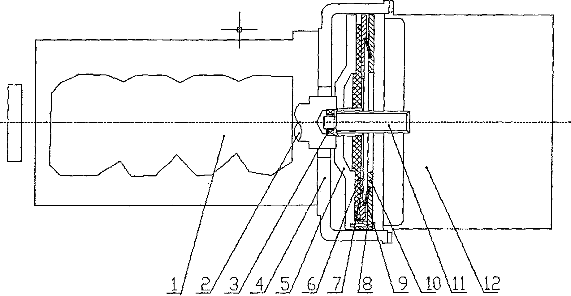
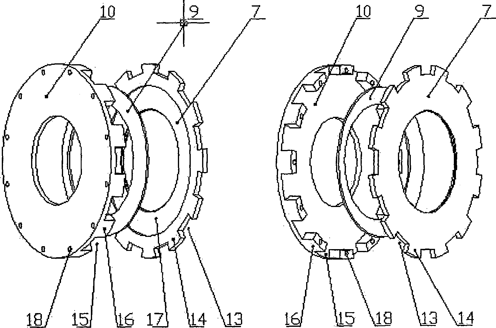
[0009] Such as figure 1 As shown, the crankshaft 2 of the engine 1 is connected with the flywheel 5 by bolts. The flywheel 5 is located in the flywheel housing 4 . Flywheel 5 disk surface is in contact with friction plate 6. The friction plate 6 is in contact with the pressing plate body 7 . The pressing plate body 7 and the pressing plate cover 10 are snap-connected, and a diaphragm spring 9 is arranged between the pressing plate body 7 and the pressing plate cover 10 . The pressure plate cover 10 is connected with the flywheel 5 through bolts 8 . The friction plate 6 is connected with the motor / generator shaft 11 through its internal spline, the crankshaft 2 is provided with a supporting bearing 3, and the end of the motor / generator shaft 11 is connected with the supporting bearing 3. Specifically, ...
PUM
 Abstract
Description
Claims
Application Information
 - R&D
- Intellectual Property
- Life Sciences
- Materials
- Tech Scout
- Unparalleled Data Quality
- Higher Quality Content
- 60% Fewer Hallucinations
Browse by: Latest US Patents, China's latest patents, Technical Efficacy Thesaurus, Application Domain, Technology Topic, Popular Technical Reports.
© 2025 PatSnap. All rights reserved.Legal|Privacy policy|Modern Slavery Act Transparency Statement|Sitemap|About US| Contact US: help@patsnap.com


