Blurring correction method and imaging device

A blur correction and blurring technology, applied in image enhancement, image communication, image data processing, etc.

Active Publication Date: 2009-05-13
OM DIGITAL SOLUTIONS CORP
View PDF5 Cites 0 Cited by
  • Summary
  • Abstract
  • Description
  • Claims
  • Application Information

AI Technical Summary

Problems solved by technology

[0006] However, in the above-mentioned conventional position alignment device, the reliability of the block matching process is judged only based on the dispersion of the density distribution of each pixel block, and the pixel blocks judged to be low in confidence are excluded from the processing object, and the same Confidence of all pixel blocks judged to be high in confidence is processed, so there is a problem that the positional shift between the two images may not be detected with high precision depending on the subject to be photographed.

Method used


Image

  • Blurring correction method and imaging device
  • Blurring correction method and imaging device
  • Blurring correction method and imaging device

Examples


Embodiment approach 1

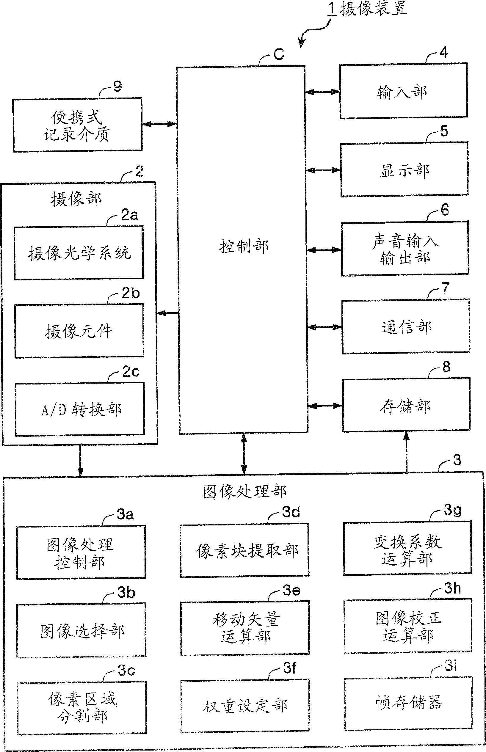
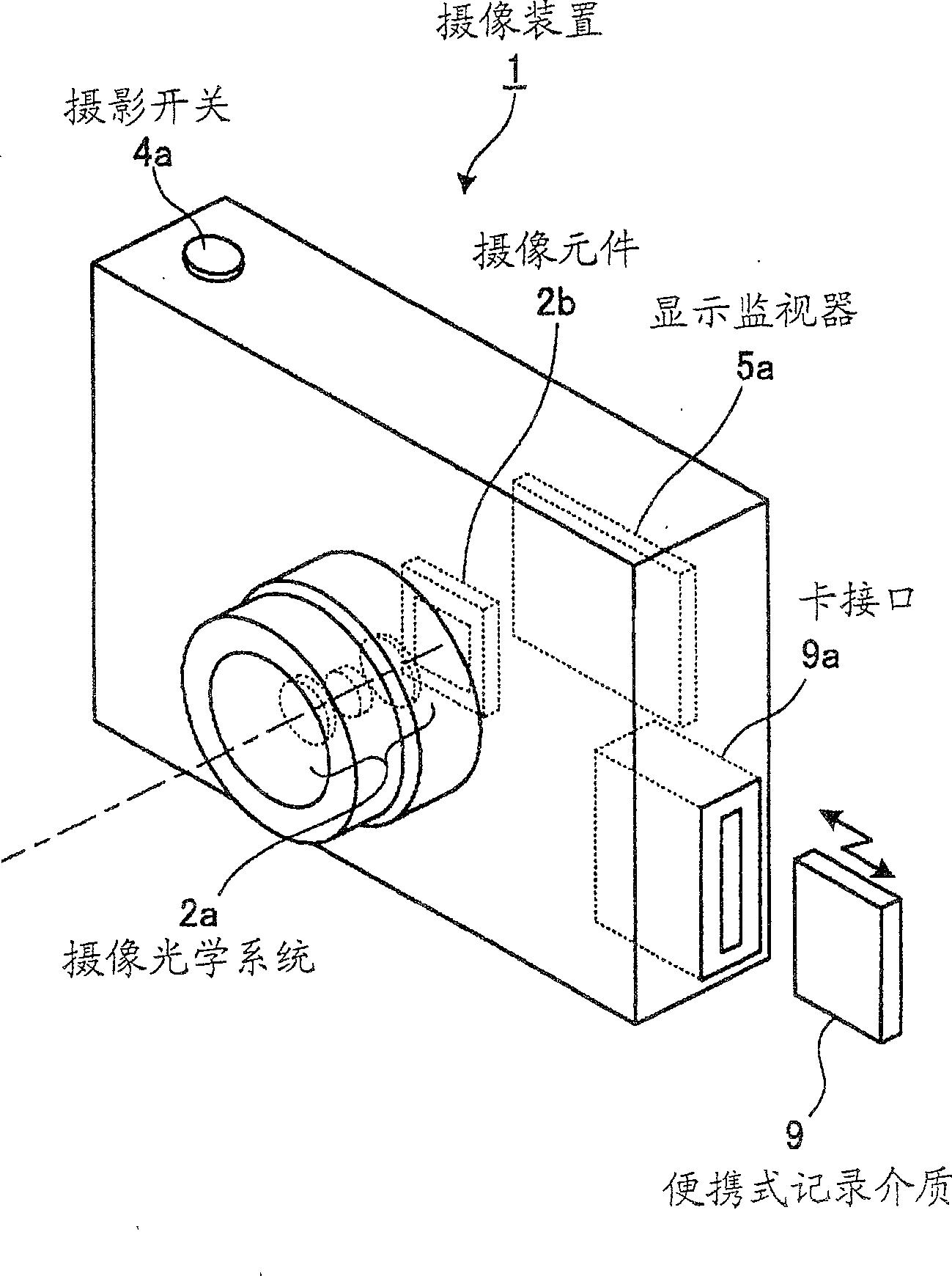
[0072] First, an imaging device according to Embodiment 1 of the present invention will be described. figure 1 It is a block diagram showing the configuration of the imaging device according to the first embodiment. figure 2 It is a perspective view showing a schematic configuration of the imaging device according to the first embodiment. Such as figure 1 As shown, the imaging device 1 according to Embodiment 1 includes: an imaging unit 2 that captures an image of a subject and generates an image signal; an image processing unit 3 that processes the image signal generated by the imaging unit 2; and an input unit that inputs various instruction information. 4; display unit 5 showing various information; voice input and output unit 6 for input and output processing of voice information; communication unit 7 for information communication between external devices; storage unit 8 for storing various information; The portable recording medium 9 that transmits and receives data th...

Embodiment approach 2

[0155] Next, Embodiment 2 of the present invention will be described. In the first embodiment described above, a plurality of target pixel blocks Bi are extracted from each pixel area As obtained by dividing the target image, and the transformation coefficients of the affine transformation corresponding to image blur are calculated with high accuracy. In 2, two target pixel blocks Bi are extracted from the four corner regions of the target image, and the transformation coefficients of the affine transformation can be calculated simply and quickly.

[0156] Figure 12 It is a schematic diagram showing an example of a state where two target pixel blocks are extracted from the corner region of the target image. Such as Figure 12 As shown, in the second embodiment, the target pixel blocks BS1 and BS2 which are the target pixel blocks Bi are respectively extracted from the lower right and upper left corner areas in the figure among the four corner areas of the target image Gt. ...


PUM


Abstract

The invention provides an image pickup device capable of calculating and correcting blur of an image with high accuracy by arithmetically processing motion vector in accordance with the reliability to blur of the image. An image pickup device 1 is provided with an image processor 3 for processing an image signal. The image processor 3 is provided with an image selector 3b for selecting an object image of an object for correcting blur of the image and a reference image of a reference of the correction, a pixel area divider 3c for dividing the object image into a plurality of pixel areas, a pixel block extractor 3d for extracting at least two object pixel blocks from the pixel areas, a motion vector arithmetic part 3e for calculating motion vector of the extracted pixel blocks, a weighting setter 3f for setting a weight coefficient of each object pixel block based on the reliability of the motion vector, a conversion coefficient calculator 3g for calculating conversion coefficient of an affine transformation corresponding to blur of the image, and an image correction calculator 3h for correcting blur by applying affine transformation to the object image based on the conversion coefficient.

Description

technical field [0001] The present invention relates to a blur correction method for correcting image blur (blur) and an imaging device that uses the blur correction method to capture an image of a subject and correct the blur of the captured image, and particularly relates to blur correction of moving images and suitable applications. A blur correction method and an imaging device for imaging. Background technique [0002] Conventionally, there is known a position alignment device that detects positional misalignment including rotation and performs position alignment of two images (for example, refer to Patent Document 1). This alignment device divides a reference image used as a reference for alignment into a plurality of pixel blocks, performs block matching processing, and detects a positional shift including rotation between the reference image and a target image to be aligned. , based on the detection result, the position alignment of the two images is performed. In ...

Claims


Application Information

Patent Timeline
Patent Type & Authority Patents(China)
IPC IPC(8): G02B27/64H04N5/232G06T5/00
Inventor 坂田诚一郎堀江健一
Owner OM DIGITAL SOLUTIONS CORP
Why Eureka
Try Eureka