Substrate transport device and operation method for substrate transport device
A technology of substrate conveying and substrate
- Summary
- Abstract
- Description
- Claims
- Application Information
AI Technical Summary
Problems solved by technology
Method used
Image
Examples
Deformed example 1
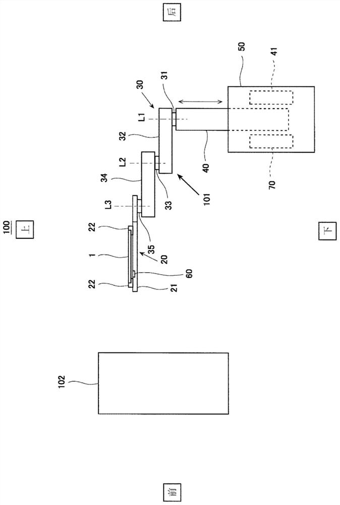
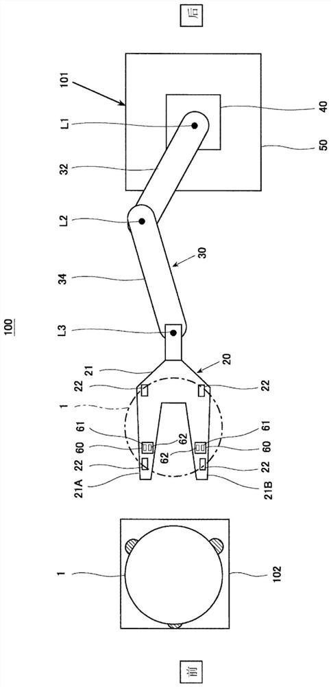
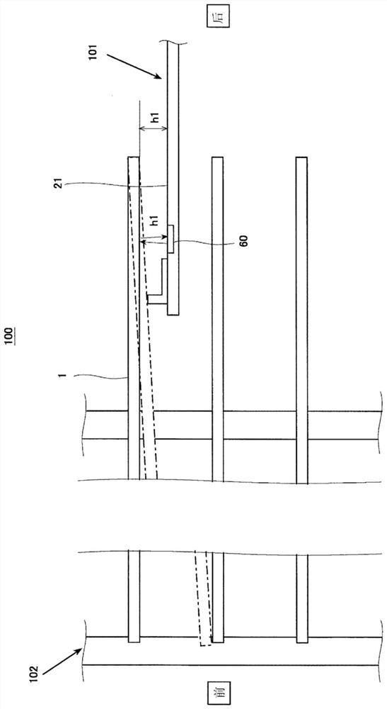
[0109] Next, edge reference Figure 7 and Figure 8 A modified example of the substrate transfer device 101 according to the first embodiment will be described.
[0110] In the substrate transfer apparatus according to Modification 1 of Embodiment 1, the first light projecting section of the substrate detector is configured to project light downward.
[0111] Figure 7 and Figure 8 It is a schematic diagram showing a schematic configuration of main parts of a substrate transfer apparatus according to Modification 1 of Embodiment 1. FIG. exist Figure 7 2 shows a substrate detector 60 configured such that the first light receiving unit 62 receives light reflected on the main surface of the substrate 1 when the substrate 1 is normally stored in the container 102 . exist Figure 8 2 shows a substrate detector 60 configured so that the first light receiving unit 62 does not receive light reflected on the main surface of the substrate 1 when the substrate 1 is normally stored ...
Embodiment approach 2
[0120] In addition to the substrate transfer device according to Embodiment 1, the substrate transfer device according to Embodiment 2 is provided with a surveying device at the front end of the robot, and the surveying device has a second light projecting unit that projects light in the horizontal direction. , and a second light receiving unit that receives light projected from the second light projecting unit, the control device is configured to obtain, from the surveying device, positional information that the second light receiving unit has not detected the light projected from the second light projecting unit as the position of the substrate The information is based on the position information of the substrate acquired from the surveying device, and the manipulator is operated so that the manipulator is positioned below a first distance previously set from the lower surface of the substrate.
[0121] In addition, in the substrate transfer device according to Embodiment 2, ...
Embodiment approach 3
[0133] Such as Figure 10 and Figure 11 As shown, the robot system 200 includes a substrate transfer device 201 and a container 112 as a mounting table. In this robot system 200 , by accommodating the substrate 1 in the container 112 , the substrate 1 is placed on the stage. The container 112 may be, for example, a FOUP (Front Opening Unified Pod) or a quartz boat.
[0134] Figure 10 The left-right direction and the up-down direction in , indicate the front-back direction and the up-down direction of the substrate transfer device 201 . in addition, Figure 11 The left-right direction of represents the front-back direction of the substrate transfer device 201 . Figure 11 The up-down direction of is downward means that the left-right direction of the substrate transfer device 201 is leftward.
[0135] The substrate 1 is, for example, a substrate of a semiconductor device such as a semiconductor substrate or a glass substrate. The substrate 1 is, for example, a circular...
PUM
 Abstract
Description
Claims
Application Information
 - R&D
- Intellectual Property
- Life Sciences
- Materials
- Tech Scout
- Unparalleled Data Quality
- Higher Quality Content
- 60% Fewer Hallucinations
Browse by: Latest US Patents, China's latest patents, Technical Efficacy Thesaurus, Application Domain, Technology Topic, Popular Technical Reports.
© 2025 PatSnap. All rights reserved.Legal|Privacy policy|Modern Slavery Act Transparency Statement|Sitemap|About US| Contact US: help@patsnap.com


