
Driveway for magnetic suspension train

A technology of maglev trains and rails, which is applied to roads, tracks, buildings, etc., to achieve the effect of simplified replacement and easy separation from each other

Inactive Publication Date: 2009-05-20
埃菲尔德国钢铁技术有限公司
View PDF9 Cites 0 Cited by
  • Summary
  • Abstract
  • Description
  • Claims
  • Application Information

AI Technical Summary

Problems solved by technology

Furthermore, the entire configuration of trusses must be replaced in the event of failure of one vertical support, since in situ repairs are not possible

Method used


Image

  • Driveway for magnetic suspension train
  • Driveway for magnetic suspension train
  • Driveway for magnetic suspension train

Examples


Embodiment Construction

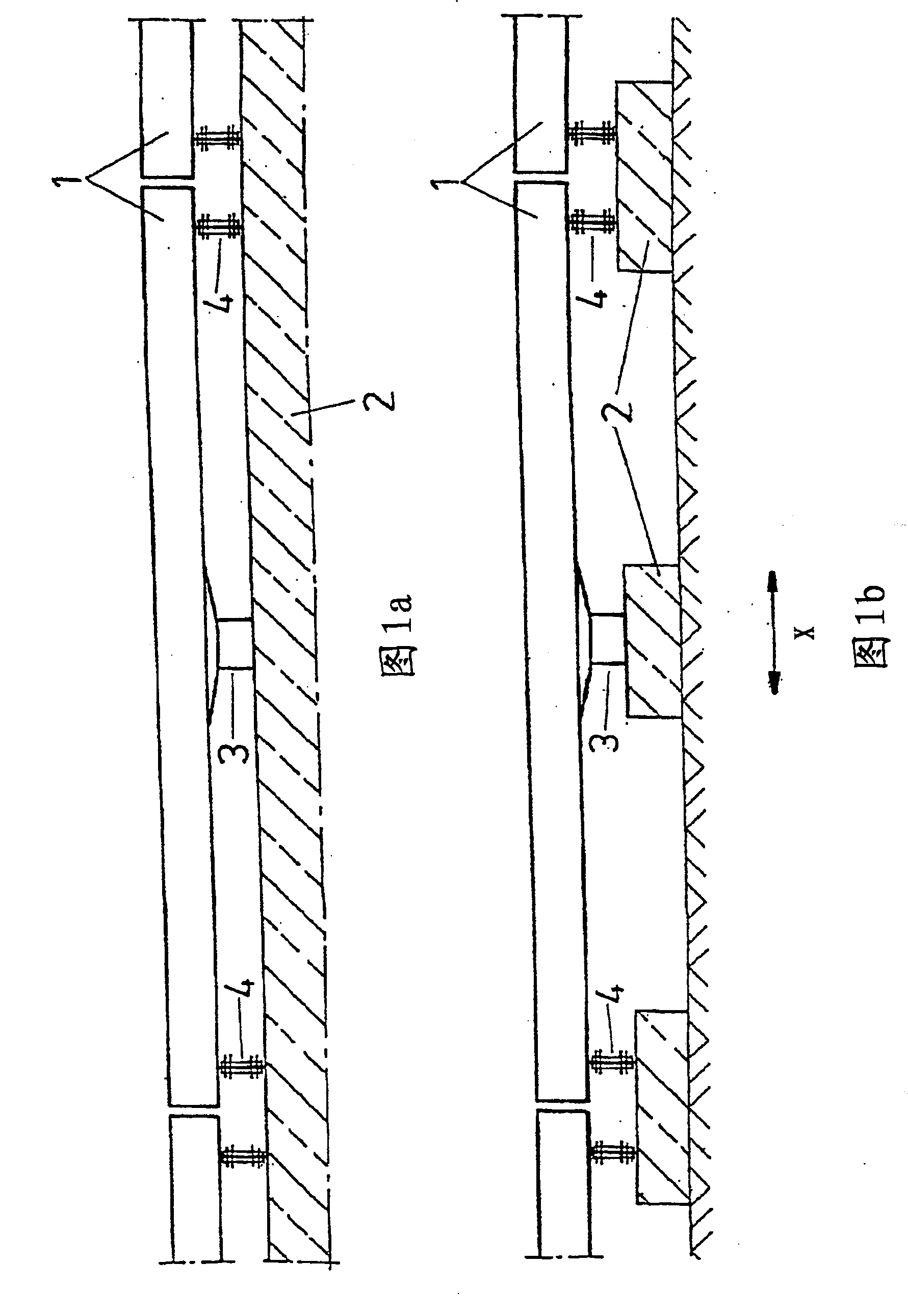
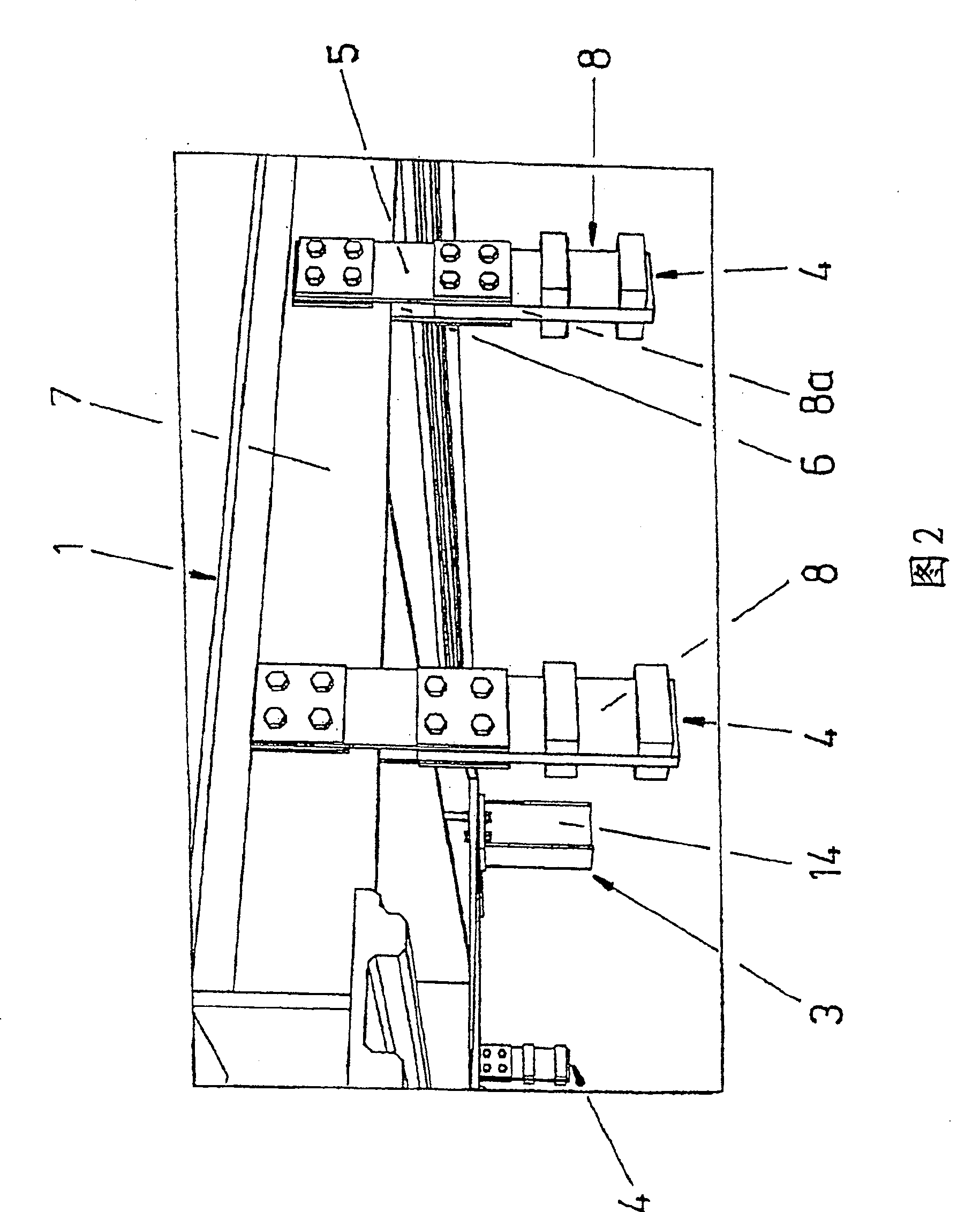
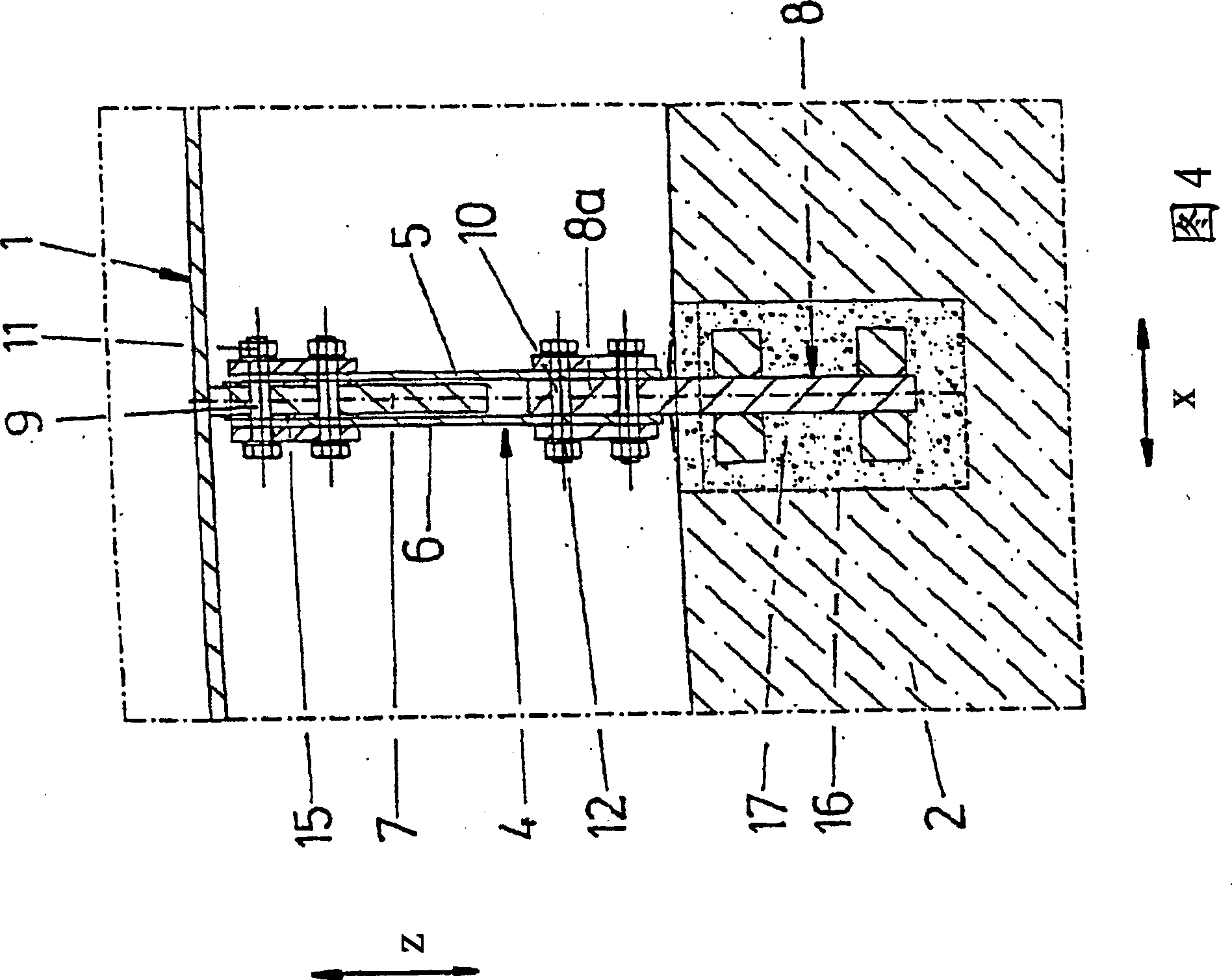
[0014] Figures 1a and 1b schematically show two schemes of a train track of a maglev train. The track comprises a plurality of track modules 1 which are arranged in series in the longitudinal direction (arrow x) and which are provided with various accessories not shown separately, such as stator laminations, side rails, sliding plates, which are necessary for the operation of the maglev train article etc. The length of each module 1 , measured in the x-direction, is eg 6.192 m, while its width, depending on the respective train type, is eg 2.80 m.

[0015] Each module 1 is supported on a main load-bearing structure 2, which involves the respective concrete foundation established on the ground (bottom in FIG. 1 ), a continuous concrete foundation in the x-direction (top in FIG. 1 ) or also for example a trolley A rail truss, itself supported on pillars on the ground or on a foundation established on the ground. For the purposes of the invention, it is in principle irrelevant ...


PUM


Abstract

The invention relates to a track for a maglev train, comprising a plurality of track modules (1) arranged along a railway line, preferably with accessories, by means of at least one fastening device (4) each having a floating bearing function ) is fixed on a main load-bearing structure (2). The fastening device (4) comprises a vertical support made of spring steel connected to the underside of the module (1), which vertical support is detachably connected to the module (1).

Description

technical field [0001] The invention relates to a running track of a magnetic levitation train. Background technique [0002] Tracks for maglev trains are known in various embodiments. It generally consists of a plurality of pillars of height 1 meter or more established along a predetermined railway line and fixed in a main load-bearing structure and a plurality of road rails arranged on the pillars with a length of, for example, about 12m to about 62m on the beam. All accessories required for the operation of the magnetic levitation train, such as stator laminations, side guide rails, sliding slats, etc., are fastened to the girders. In the application of steel truss girders, in order to have the necessary thermal expansion, it is fixedly supported in a middle part and is movably supported in the manner of floating bearings at each end part on the corresponding struts. The floating bearing is formed, for example, as an elastomer polytetrafluoroethylene (Teflon) sliding b...

Claims


Application Information

Patent Timeline
Patent Type & Authority Patents(China)
IPC IPC(8): E01B25/30E01B25/32
CPCE01B25/305E01B25/32
Inventor 约翰·马图舍克托马斯·施蒂尔
Owner 埃菲尔德国钢铁技术有限公司
Learn More