
Lens grinding method and device

A lens and grinding technology, used in grinding/polishing equipment, grinders, optical surface grinders, etc., can solve the problems of no consideration, processing time loss, etc., and achieve the effect of reducing resistance, avoiding waste, and inhibiting wear and tear

Inactive Publication Date: 2009-05-27
HARUCHIKA
View PDF4 Cites 0 Cited by
  • Summary
  • Abstract
  • Description
  • Claims
  • Application Information

AI Technical Summary

Problems solved by technology

However, in the past, machining was performed at the same cutting speed without any consideration for this point, so the machining time was lost

Method used


Image

  • Lens grinding method and device
  • Lens grinding method and device
  • Lens grinding method and device

Examples


Embodiment Construction

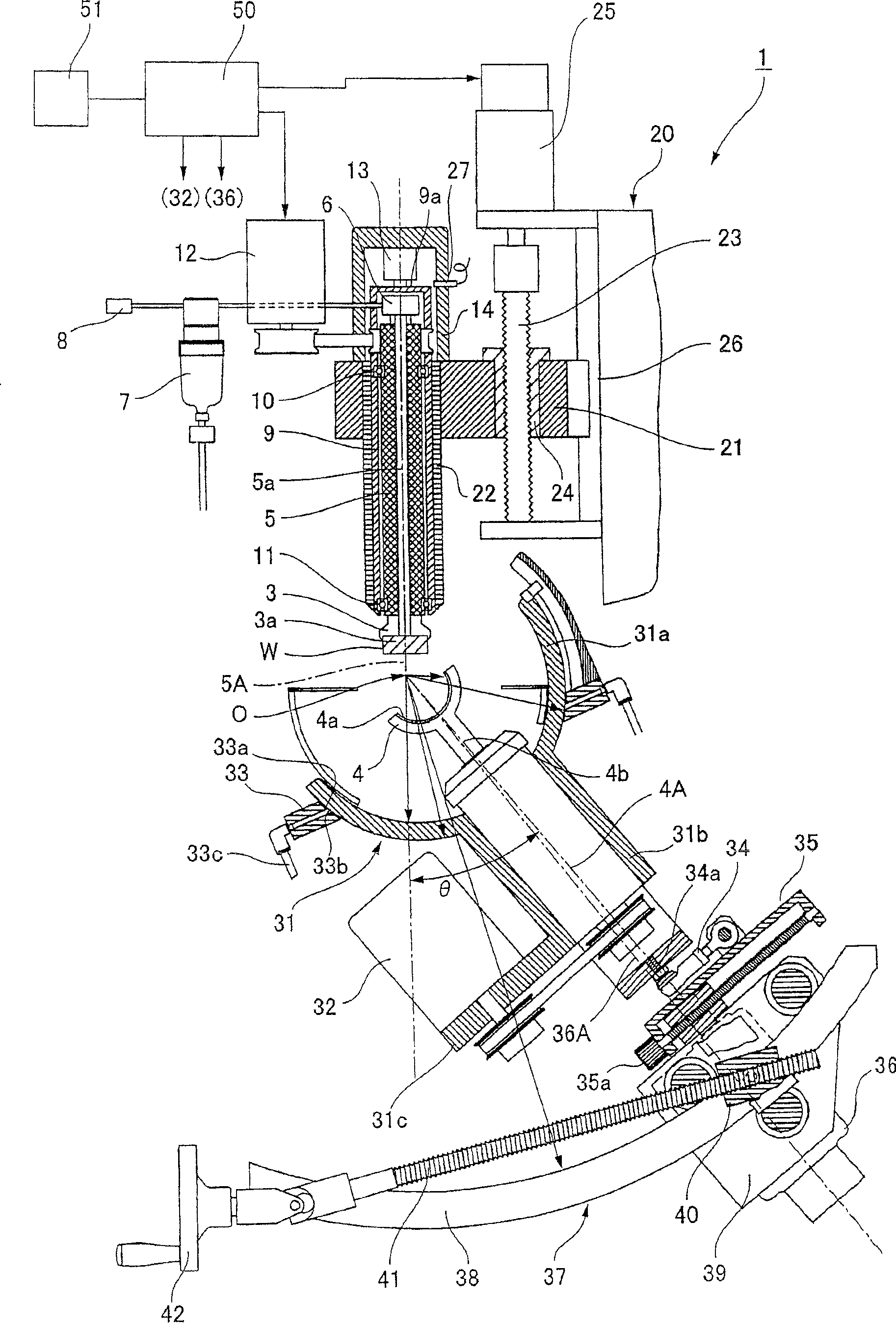
[0036] Hereinafter, an embodiment of a grinding apparatus for an optical spherical lens to which the present invention is applied will be described with reference to the drawings.

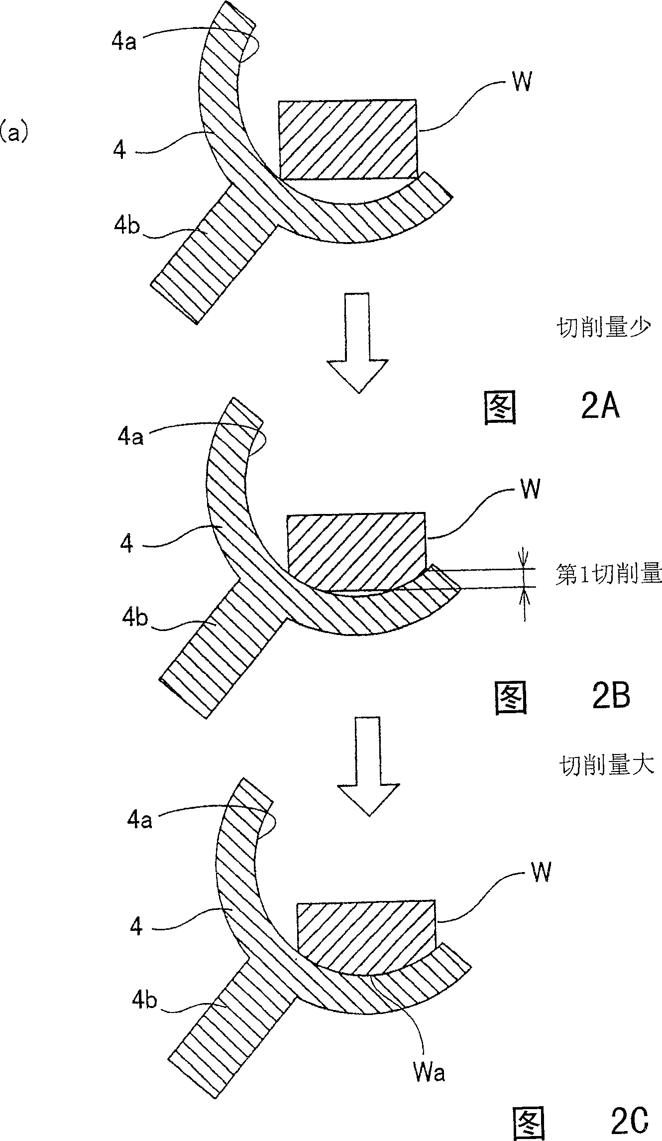
[0037] figure 1 It is a schematic configuration diagram showing a main part of the grinding apparatus for an optical spherical lens according to the present embodiment. Described with reference to this figure, the grinding device 1 has: a lens holder 3 for holding a lens blank W to be processed; and a spherical grinding surface 4a for grinding the lens blank W held on the lens holder 3 The bowl tool 4.

[0038]The lens holder 3 is fixed to the lower end of the vertical lens main shaft 5 with its holding surface 3 a held horizontally downward. At the center of the lens main shaft 5, a suction passage 5a extending toward its axis is formed, its lower end opens to the center of the holding surface 3a of the lens holder 3, and its upper end passes through the connection between the rotary joint 6, t...


PUM


Abstract

In the lens grinding apparatus of the present invention, while the grinding bowl-shaped tool with spherical grinding surface rotates around the rotary central line through the sphere center and the rotary central line performs sphere center swinging to describe one cone with the sphere center as vertex, the lens blank is fed in specified rate in the feeding direction through the sphere center and pushed towards the bowl-shaped tool for grinding, with the cutting speed being altered based on the lens blank feeding speed. The said lens grinding process can cut lens material in high efficiency and grind spherical lens with small curvature in high precision.

Description

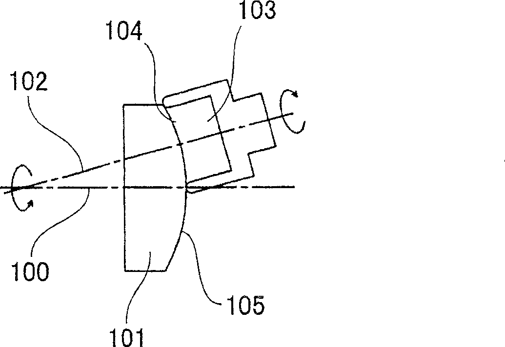
technical field [0001] The present invention relates to a lens grinding method and a lens grinding device for grinding an optical spherical lens. More specifically, it relates to grinding a spherical lens with high precision without partial wear of a bowl-shaped tool. A lens grinding method and a lens grinding device capable of efficiently performing grinding in a short time. Background technique [0002] As a method of grinding an optical spherical lens, there is known a spherical surface manufacturing method using a cup wheel. In this method, as image 3 As shown, a glass blank 101 to be processed that rotates around an axis 100 is ground while contacting a spherical grinding surface 104 of a cup wheel 103 that rotates around an axis 102 to obtain A spherical surface 105 with the intersection of the axes 100, 102 as the center. This processing method is a method of forming a complete spherical surface, but there are problems such as irregularity in curvature due to wear ...

Claims


Application Information

Patent Timeline
Patent Type & Authority Patents(China)
IPC IPC(8): B24B13/02
Inventor 春日洋一
Owner HARUCHIKA
Learn More