Micro-connector and its terminal shape production method

A micro-connector and connector technology, which is applied to the parts of the connection device, the device for connecting, engaging/disconnecting the connected parts, etc., can solve the problems of test time and cost waste, terminal wear, high insertion force, etc., and achieve The effect of saving test time and cost, reducing the size of the device, and reducing the overall size

Active Publication Date: 2009-06-03
IND TECH RES INST
View PDF13 Cites 1 Cited by
  • Summary
  • Abstract
  • Description
  • Claims
  • Application Information

AI Technical Summary

Problems solved by technology

[0007] At the same time, the existing micro-electromechanical system (MEMS) components must first go through processes such as wire bonding or solder ball bonding, and the component function test can only be completed after the component is connected to the test fixture. Or the way of combining solder balls to package the components once, not only can not be reworked, but also the related test fixtures can not be reused, so the waste of test time and cost
In addition, most of the prior art mentioned above has a high insertion force, causing wear to the terminals
Moreover, due to the thermal effect caused by high temperature in the manufacturing process, the terminal will bend downward when the female terminal structure is released, and the electrical signal connection cannot be completed when the male and female terminals are mated; The female terminal is bent and damaged when the terminal is plugged in (Kinking effect)
[0008] Due to the high insertion force and excessive overall size of the above-mentioned prior art, it is not conducive to the design of multi-terminal connectors, no impedance matching design, no electromagnetic wave interference prevention design, and no hostage mechanism design. Therefore, how to solve various problems derived from the prior art The shortcomings have become an urgent problem to be solved

Method used


Image

  • Micro-connector and its terminal shape production method
  • Micro-connector and its terminal shape production method
  • Micro-connector and its terminal shape production method

Examples


Embodiment 1

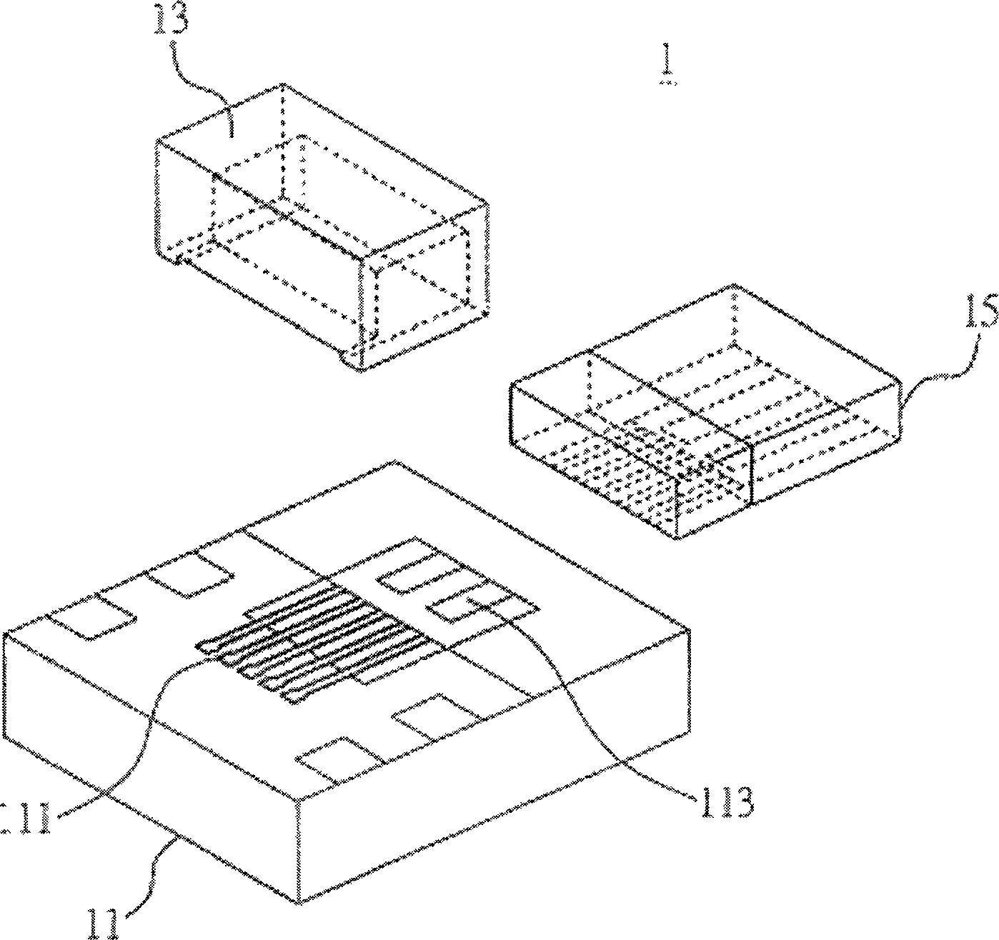
[0045] Figures 1 to 11C It is drawn according to Embodiment 1 of the manufacturing method of the miniature connector and its terminal shape of the present invention. Such as figure 1 As shown, the micro connector 1 includes a base 11 , a cover 13 and an insert 15 .

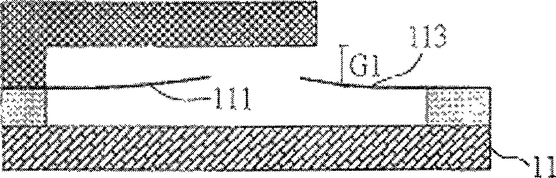
[0046] The base 11 has a first conductive connection portion 111 and a barb portion 113 . In the first embodiment, the base 11 can be made of materials such as silicon, and the first conductive connection part 111 can be composed of a plurality of female terminals, and the barb part 113 can be, for example, a shrapnel, and make the first conductive The end of the connecting portion 111 and the barb portion 113 is an arc structure bent upwards. The method of forming the first conductive connection portion 111 and the barb portion 113 on the base 11 will be described in detail later.

[0047] Such as figure 2 As shown, the cover 13 is arranged on the base 11, and forms a gap G1 (first gap) with the first cond...

Embodiment 2

[0059] Figure 12 It is drawn according to Embodiment 2 of the present invention. Wherein, components identical or similar to those in Embodiment 1 above are represented by identical or similar component symbols, and detailed descriptions are omitted to make the description of this case clearer and easier to understand.

[0060] Different from the first embodiment above, the cover 13 of this embodiment forms a chamfer 137 on the edge of the third recess 135 corresponding to the gap G1, making it easier for the insert 15 to be inserted into the cover 13 and the base 11 between. Certainly, those skilled in the art know that the size of the chamfer 137 is not limited to that described in this embodiment. In this way, the insertion force can be further reduced.


PUM


Abstract

A minisize connector and the method of the terminal shape, the minisize connector includes: the base, the covering piece and the inserting piece, the base combine with the covering piece as the mother end, the inserting piece inserts between the base and the covering piece as the father end, reduces the distance of the terminal and the size of the whole body, provides the effects that are the low inserting force, the low static actuating force effect and the fixing inserting piece. The invention is: the anti-electromagnetic interference, the adjustable terminal impedance, the low cost.

Description

technical field [0001] The present invention relates to an electrical connection technology, in particular to a method for making a miniature connector and its terminal shape. Background technique [0002] The function of a common connector is to provide a separable interface, connect the subsystems inside the electronic system, and transmit signals or power. Due to the long-term application of connectors, the number of related patents is quite large, such as US Patent No. 4,176,900, No. 4,330,163, No. 4,630,874, No. 4,636,021, No. 4,684,194, No. Patent No. 6,817,776, Taiwan Invention Patent Announcement No. 595826, and Taiwan Utility Model Patent Certificate No. M260896, etc. [0003] In order to maintain a stable contact interface when the electronic system is running, conventional connectors generate a normal contact force on the contact interface. However, since more and more pins are designed on the connectors used by integrated circuits and printed circuit boards tod...

Claims


Application Information

Patent Timeline
Patent Type & Authority Patents(China)
IPC IPC(8): H01R13/62H01R13/629H01R13/11H01R13/46H01R13/646H01R43/16
Inventor 章本华林欣卫方维伦苏旺申
Owner IND TECH RES INST
Why Eureka
Try Eureka