

Vibration-damper application system
An application system and technology of shock absorbing devices, applied in liquid shock absorbers, instruments, electrical digital data processing, etc., can solve the problems of inability to be placed in motor vehicles, low shock resistance, etc., to improve practicability and work reliability, The effect of reducing the load on the bottom and preventing excessive subsidence
- Summary
- Abstract
- Description
- Claims
- Application Information
AI Technical Summary
Problems solved by technology
Method used
Image

Examples
Embodiment 1
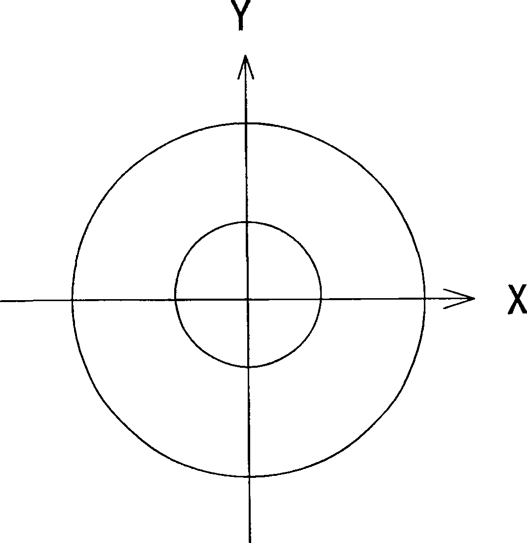
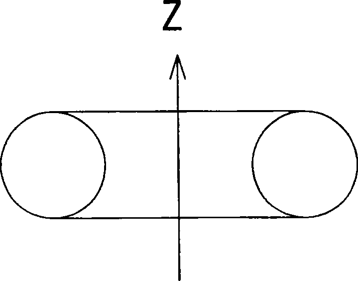
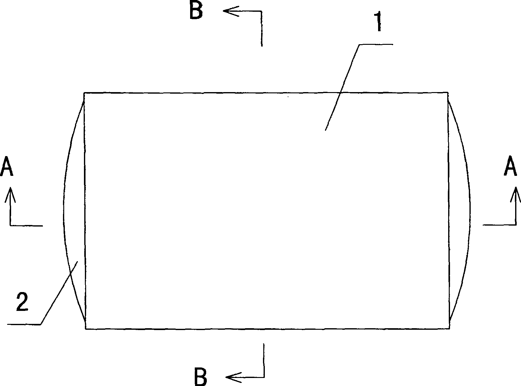
[0040] according to image 3 , Figure 4 and Figure 5 , the present invention comprises a hard shell 1, a ring body elastic sleeve 2 is arranged in the hard shell 1, the ring body elastic sleeve 2 includes an elastic closed ring body space 21, the outer side of the ring body elastic sleeve 2 and the hard shell 1 The inner wall of the ring body is squeezed against each other, and the inner side of the ring body elastic sleeve 2 covers the accommodating space 22. In fact, in the present invention, the ring body elastic sleeve 2 is in a shape similar to an automobile inner tube, such as figure 1 and figure 2 As shown, in the free state (without external force), the annular body elastic sleeve 2 is consistent with the topological shape of the automobile inner tube.
[0041] In the present invention, the ring body elastic sleeve 2 is a ring body rubber sleeve, such as Figure 4 and Figure 5 As shown, the rubber sleeve surface 201 and the rubber sleeve surface 202 jointly co...
Embodiment 2
[0048] Such as Figure 6 and Figure 7 As shown, the difference between this embodiment and Embodiment 2 is that in this embodiment, a partition 211 is provided in the closed ring space 21, and a through hole 212 is provided on the partition 211, such as Figure 6 As shown, the partitions 211 are disposed on both horizontally symmetrical sides with the accommodating space 22 as a symmetry axis (ie, the plane of the partitions 211 is perpendicular to the Y-axis).
[0049] Such as Figure 6 and Figure 7 As shown, the partition 211 and the through hole 212 on it can further restrict the direction and speed of the flow of the viscous liquid (filler), which is used to adjust the elasticity, rigidity and damping coefficient of the present invention to achieve the best shock absorption effect .
Embodiment 3
[0051] according to Figure 8 , Figure 9 and Figure 10 , the difference between this embodiment and embodiment 1 or 2 is: in this embodiment, if Figure 8 As shown, an elastic device 301 is connected between the load / electronic equipment (such as a hard disk HDD) in the accommodating space 22 and the hard shell 1, and the elastic device 301 provides a buffer force to the load / electronic equipment to prevent the load / electronic Excessive subsidence of the device, causing too much viscous liquid (filler) in the lower part of the annular body elastic sleeve 2 to be pushed away and the load / electronics to hit the hard case 1 .
[0052] Such as Figure 8 As shown, it only reflects that the elastic device 301 is erected on one side of the load / electronic device. In practical applications, the elastic device 301 may be erected on both sides of the load / electronic device.
[0053] In the present invention, as Figure 9 As shown, the elastic device 301 includes a spring 302 and ...
PUM
 Abstract
Description
Claims
Application Information