Rolling device

A rolling mill frame, work roll technology, applied in the direction of metal rolling, metal rolling, counter pressure devices, etc., can solve the problems of damaged bearings, guide work roll bearing housings, can not be guaranteed, etc., to avoid tilting, compact The effect of structural form

Active Publication Date: 2009-07-01
SMS DEMAG AG
View PDF7 Cites 2 Cited by
  • Summary
  • Abstract
  • Description
  • Claims
  • Application Information

AI Technical Summary

Problems solved by technology

Therefore, it cannot be ruled out that a local side pressure may be generated when the stand is subjected to impact loading by rolling forces after the work rolls have moved ("track impact") and thus lead to long-term damage to the bearing, e.g. in the case of oil friction bearings. Damage to the bushing or journal bushing or, in rolling bearings, overloading of individual bearing rows
[0013] It is theref

Method used


Image

  • Rolling device
  • Rolling device
  • Rolling device

Examples


Example Embodiment

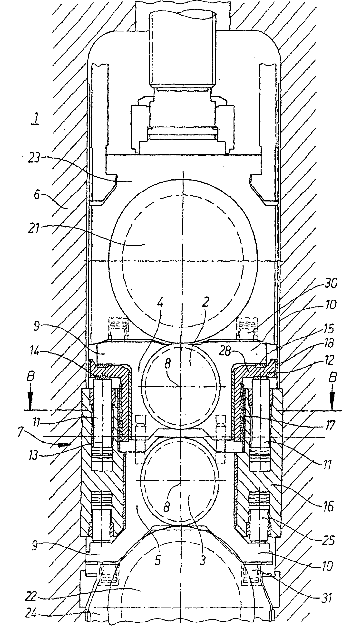
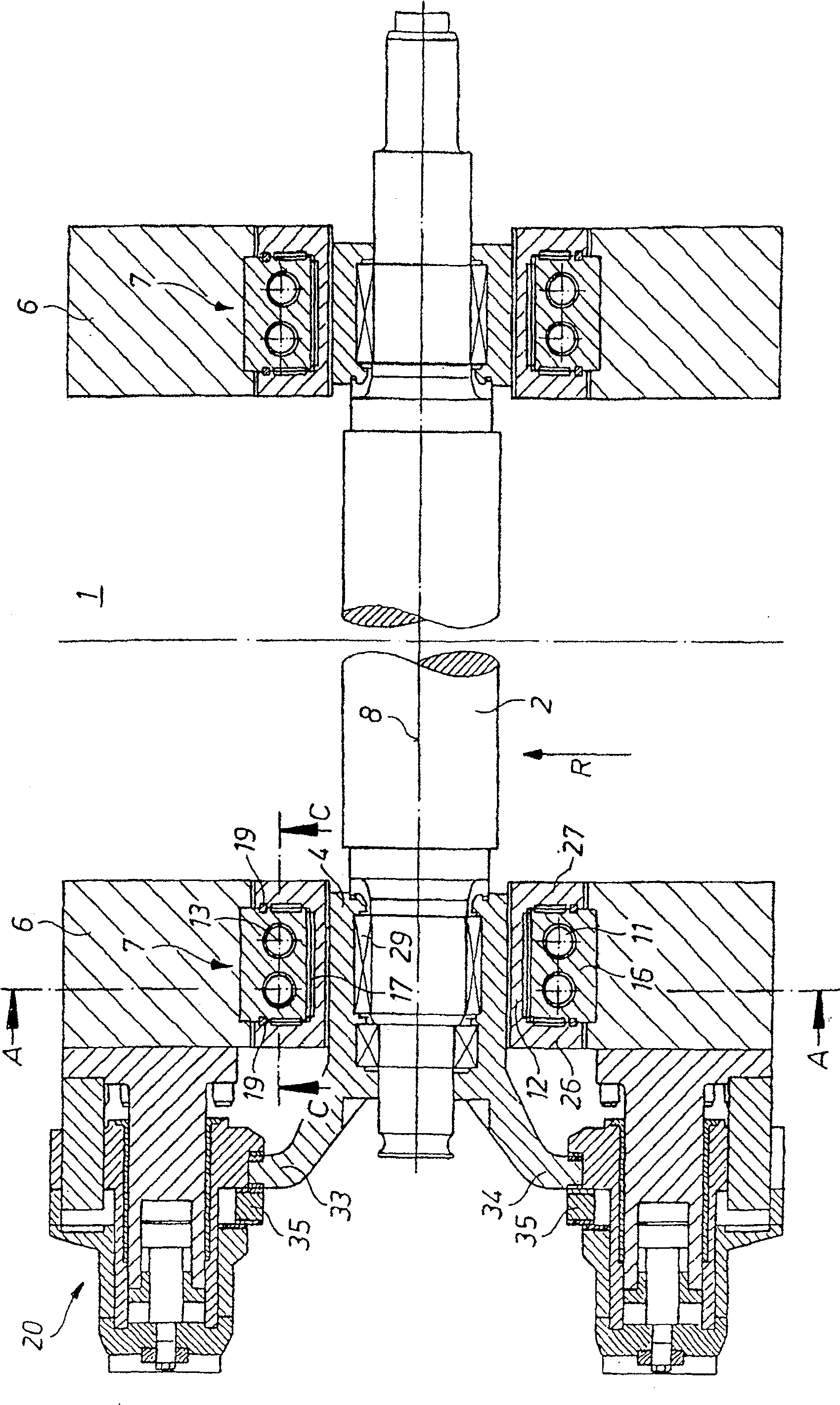
[0039] in figure 1 3 shows a rolling device 1 in which two cooperating work rolls 2 and 3 are arranged in a rolling mill stand 6, and the work rolls are supported in a work roll chock 4 or 5, respectively.

[0040] In order to arbitrarily adjust the roll gap between the two work rolls 2 and 3 to a large extent, the upper work roll chock 4 can be adjusted in the vertical direction; that is, it can be relative to the rolling mill stand 6 in the vertical direction. mobile.

[0041] The work rolls 2 and 3 are respectively supported on a supporting roll 21 or 22, wherein these supporting rolls are supported in a supporting roll chock 23 or 24, respectively. The rolling device 1 has a total of four rolls. It should be noted that it can also have other rolls, namely intermediate rolls arranged between the work rolls 2, 3 and the support rolls 21, 22.

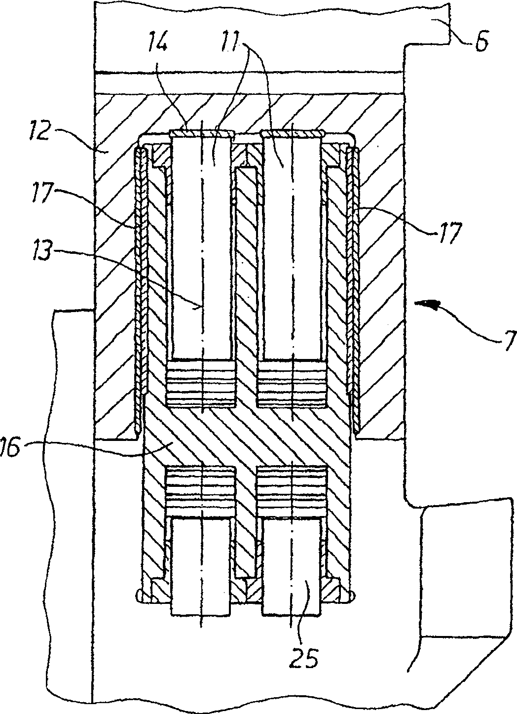
[0042] In order to introduce the bending moment to the work rolls 2 and 3, a bending mechanism 7 is provided. As especially by figure 2 ...


PUM


Abstract

The invention relates to a rolling installation (1), which has at least two work rolls (2, 3), which are each mounted in a rolling stand (6) via work roll chocks (4, 5), wherein at least A work roll (2, 3) can be adjusted in the rolling stand (6) in particular vertically relative to the other work roll (2, 3) in order to set a desired roll gap, wherein at least one work roll (2, 3) It is in active connection with the bending mechanism (7), through which the work roll can be loaded with a bending moment, and wherein the work roll chocks (4, 5) are designed to bear the force generated by the bending mechanism (7) The force has side projecting arms (9, 10) viewed from the work roll (2, 3) axis (8). In order to improve the adjustability of the rolling unit over a large lift, according to the invention it is provided that the elements (11) of the pressure-generating bending mechanism (7), in particular the pistons and the work roll chocks (4, 5) Between the protruding arms (9, 10) there is arranged a pressure transmission element (12) which is movable relative to the rolling stand (6), especially in the vertical direction.

Description

technical field [0001] The invention relates to a rolling installation with at least two work rolls, which are each mounted via a work roll chock in a roll stand, wherein at least one work roll is positioned in the roll stand in order to adjust a desired The roll gap can be adjusted relative to another working roll, in particular in the vertical direction, at least one of the working rolls being operatively connected to a bending mechanism, through which this working roll can be loaded with a bending moment, and wherein the working roll The roll chock has side protruding arms viewed from the work roll axis in order to withstand the force generated by the bending mechanism. Background technique [0002] Rolling devices of this type are already known in the prior art. See, for example, EP 0 256 408 A2, EP 0 256 410 A2, DE 38 07 628 C2 and EP 0 340 504 B1. Rolling installations are known from these documents in which two work rolls with a defined distance form the roll gap ne...

Claims


Application Information

Patent Timeline
IPC IPC(8): B21B29/00B21B31/18B21B31/20
CPCB21B29/00B21B31/203B21B31/18B21B31/16B21B31/20
Inventor B·齐泽尔A·克莱因F·林德纳C·迪尔
Owner SMS DEMAG AG
Why Eureka
Try Eureka