Dual L seamless high power electronic ballast housing

An electronic ballast, fit-type technology, applied in the direction of electric light sources, electrical components, lighting devices, etc., can solve problems such as high-power radio frequency interference, unreasonable technology, circuit instability, etc., to improve electromagnetic compatibility and heat dissipation effect Obvious, easy to install and debug effect

Inactive Publication Date: 2009-07-01
SHANGHAI NAT ENG RES CENT FORNANOTECH
View PDF5 Cites 0 Cited by
  • Summary
  • Abstract
  • Description
  • Claims
  • Application Information

AI Technical Summary

Problems solved by technology

"Its disadvantage is that it is not only extremely difficult to install the high-power tubes at the bottom of the shell, but also the heat source is concentrated and it is not conducive to heat dissipation.
If debugging and maintenance cannot be carried out after installation, it will be very troublesome and unreasonable process
In addition, installing the high-power tubes of the PFC circuit and the high-power tubes of the half-bridge circuit together will cause serious high-power radio frequency interference between each other, making the circuit itself extremely unstable

Method used


Image

  • Dual L seamless high power electronic ballast housing
  • Dual L seamless high power electronic ballast housing

Examples


Embodiment Construction

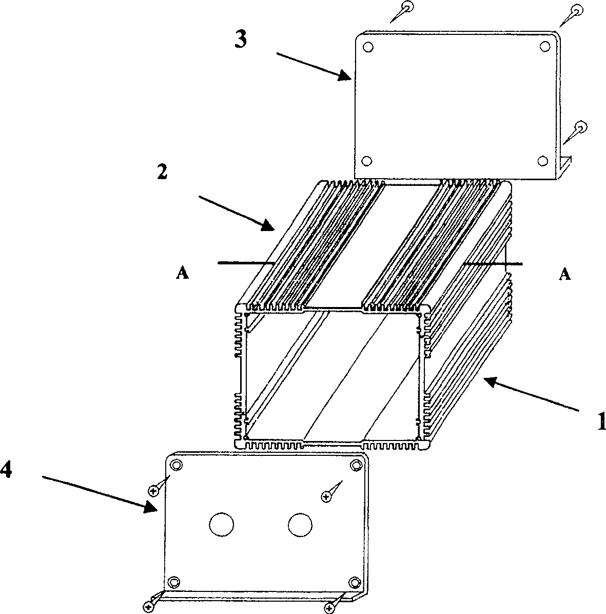
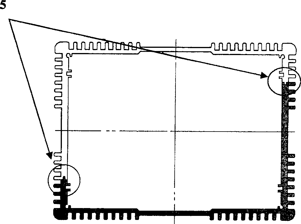
[0013] Such as figure 1 As shown, the present invention includes: a lower L-shaped housing 1, an upper L-shaped housing 2, a first side cover 3, a second side cover 4, two concave-convex joint points 5, and two lower L-shaped housings with exactly the same shape and size. The upper L-shaped housing 1 and the upper L-shaped housing 2 form an L-shaped main housing through the relative engagement of two concave-convex joint points 5. The two ends of the L-shaped main housing have a square cross-section. The first side cover 3 and the second side cover 4 is fixed on the cross section at both ends of the L-shaped main casing by screws, and the two concave-convex joint points 5 are concave and convex with the same nominal size.

[0014] For the two concave-convex matching points 5, the concave shape is selected with a positive tolerance, and the convex shape is selected with a negative tolerance, so that a three-level interference fit is maintained during the fit.

[0015] The center di...


PUM


Abstract

This invention relates to a shell of a double-conjugated L-shaped large power electronic ballast including: a lower L-shaped shell, an upper L-shaped shell, a first side cover, a second side cover, two convex / concave points, in which, the two L-shaped shells in a same shape and size form a master shell by conjugating the two points, the end surfaces of both sides of the master shell are square, the two side covers are fixed at the cross sections of both ends and the two conjugated points are in the shape of the nominal convex / concave .

Description

Technical field [0001] The invention relates to a shell, specifically, a double L-fit type high-power electronic ballast shell, which belongs to the technical field of electronic assembly. Background technique [0002] In the past, various types of high-power electronic ballast shells generally have the following problems: The circuit board can only be installed when everything is well debugged. It cannot be debugged or inspected and repaired after installation. High-power tubes are generally fixed on the shell by screws to achieve the heat dissipation effect, but it is very difficult to install. [0003] A literature search of the prior art found: Chinese Patent Publication No. 1376024, the publication date was October 23, 2002, and the patent name was: Power Electronic Ballast Sealed Heat Dissipating Shell. The patent reads: "The disclosure of the present invention Power electronic ballast sealed heat dissipation shell, the shell is in the shape of a cuboid, the shell is provid...

Claims


Application Information

Patent Timeline
Patent Type & Authority Patents(China)
IPC IPC(8): H05B41/02H05K7/20
Inventor 张伟韩杰
Owner SHANGHAI NAT ENG RES CENT FORNANOTECH
Why Eureka
Try Eureka