Sewing machine

A sewing machine and spindle technology, applied to sewing machine components, needle holders for sewing machines, sewing equipment, etc., can solve the problems of vibration and noise, difficulty, complicated structure of sewing machine arms, etc., and achieve the effect of stable reciprocating rotation and simplified structure

Inactive Publication Date: 2009-07-08
YAMATO SEWING MASCH MFG CO LTD
View PDF5 Cites 0 Cited by
  • Summary
  • Abstract
  • Description
  • Claims
  • Application Information

AI Technical Summary

Problems solved by technology

[0010] However, in the sewing machine disclosed in Document 1, since there is a large swing arm that swings inside the sewing machine arm and a large crank arm that moves up and down inside the sewing machine body, the sewing machine may operate due to the reaction force accompanying this movement. Inappropriate situations such as large vibrations and sounds associated with the vibrations are similar to those of the sewing machine disclosed in Document 2, inappropriate situations such as vibrations and noises associated with the up and down motion of the large crank arm, It is difficult to develop towards high-speed sewing
[0011] And as in the above straight cylinder sewing machine, same as many industrial sewing machines, on the front end of the sewing machine arm, although there are assembly devices such as a spreader thread handling apparatus, but disclosed in documents 1 and 2 In the sewing machine, the transmission mechanism to the assembly device is also the same as the transmission mechanism of the needle bar, which is a complex structure necessary for a large-scale component, and there is an inside of the sewing machine arm where the transmission mechanism and the transmission mechanism of the needle bar are arranged together. construct complex problems

Method used


Image

  • Sewing machine
  • Sewing machine
  • Sewing machine

Examples


Embodiment Construction

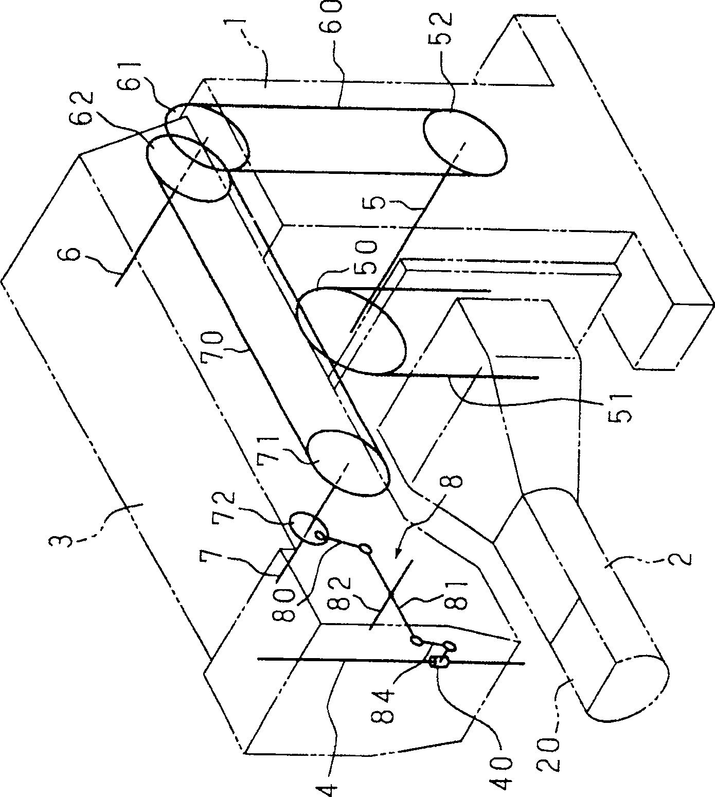
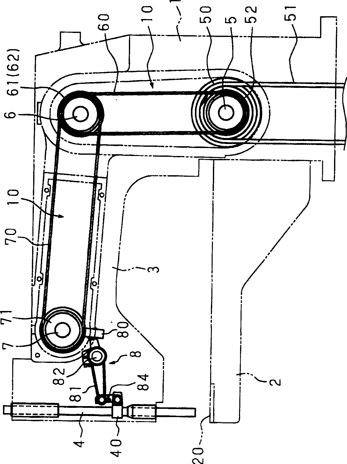
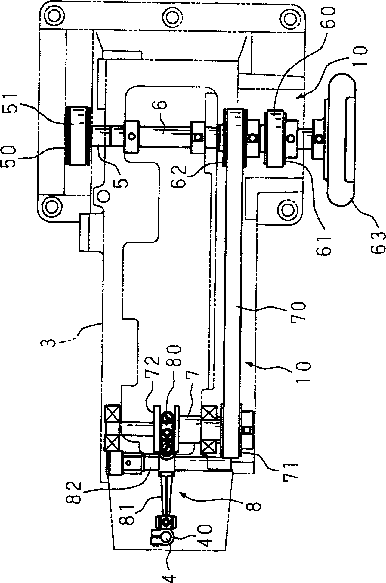
[0037] Hereinafter, the present invention will be described in detail based on the drawings showing the embodiments. figure 1 It is a perspective view showing the overall structure of the transmission mechanism of the needle bar in the sewing machine of the present invention together with the appearance of the sewing machine. In the illustrated sewing machine, the cylindrical base 2 is protruded from the lower part of the sewing machine body 1, and at the upper part on the same side, the sewing machine arm 3 is projected slightly parallel to the cylindrical base 2, thereby forming a straight cylindrical sewing machine.

[0038] This sewing machine has a feeding device and a yarn bending wheel (not shown) under the needle plate 20 mounted on the front end of the cylindrical base 2, and also has a needle bar 4 suspended and supported on the front end of the sewing machine arm 3. , a needle not shown is installed at the lower end of the needle bar 4 . In addition, at the front e...


PUM


Abstract

A transmission shaft is installed on the upper part inside of the body of the sewing machine in a way essentially parallel to the main shaft of the sewing machine installed on the lower part inside of the body of the sewing machine. A needle rod drive shaft is installed on the front end of a sewing machine arm in a way roughly parallel to the main shaft and the transmission shaft of the sewing machine. A transmission belt is separately installed between the main shaft and the transmission shaft of the sewing machine, and between the transmission shaft and the needle rod drive shaft. Through the rotation of the belt, the rotation of the main shaft of the sewing machine is transmitted to the transmission shaft and the needle rod drive shaft, and then to a rotation location near the drive shaft of the needle rod. The up-and-down reciprocation structure of the needle rod can prevent the generation of noise and the vibration of the main shaft of the sewing machine caused by the needle rod that is upwardly protruded on the front end of the sewing machine arm about orthogonal to the main shaft of the sewing machine.

Description

technical field [0001] The present invention contemplates a sewing machine, which has a front end portion of a sewing machine arm protruding from the sewing machine body in a direction substantially perpendicular to the main shaft of the sewing machine that is hung down to transmit the rotation of the main shaft of the sewing machine installed inside the main shaft of the sewing machine. Supported needle bar (needlebar), so that the structure of the needle bar up and down. Background technique [0002] The tubular parts such as sleeves and trunks of various clothing materials are formed by rolling fabric cut into a predetermined shape into a tubular shape, overlapping edges of appropriate width, and stitching each other. In order to carry out such sewing, the rolled cloth is passed through the front end of a thin cylinder bed, and an axial feed is applied from the front end to the bottom end of the cylindrical bed. And the sewing machine that sews, namely known so-called st...

Claims


Application Information

Patent Timeline
Patent Type & Authority Patents(China)
IPC IPC(8): D05B55/14D05B69/00
CPCD05B55/14D05B69/02D05B69/32
Inventor 清水好秀小松邦彦
Owner YAMATO SEWING MASCH MFG CO LTD
Why Eureka
Try Eureka