
Ball bearing producing apparatus and ball bearing producing method

A ball bearing and manufacturing device technology, applied in the direction of bearings, bearing components, shafts and bearings, can solve the problems of crown cage deformation, time-consuming maintenance, etc., and achieve the effect of preventing wear and tear

Active Publication Date: 2009-07-08
SEIKO INSTR INC
View PDF6 Cites 0 Cited by
  • Summary
  • Abstract
  • Description
  • Claims
  • Application Information

AI Technical Summary

Problems solved by technology

Therefore, it is necessary to frequently replace the ring-shaped assembly parts, so that maintenance takes a lot of time
[0008] In addition, when the crown cage is inserted between the inner and outer rings, the crown cage may interfere with the ring assembly and deform

Method used


Image

  • Ball bearing producing apparatus and ball bearing producing method
  • Ball bearing producing apparatus and ball bearing producing method
  • Ball bearing producing apparatus and ball bearing producing method

Examples


Embodiment Construction

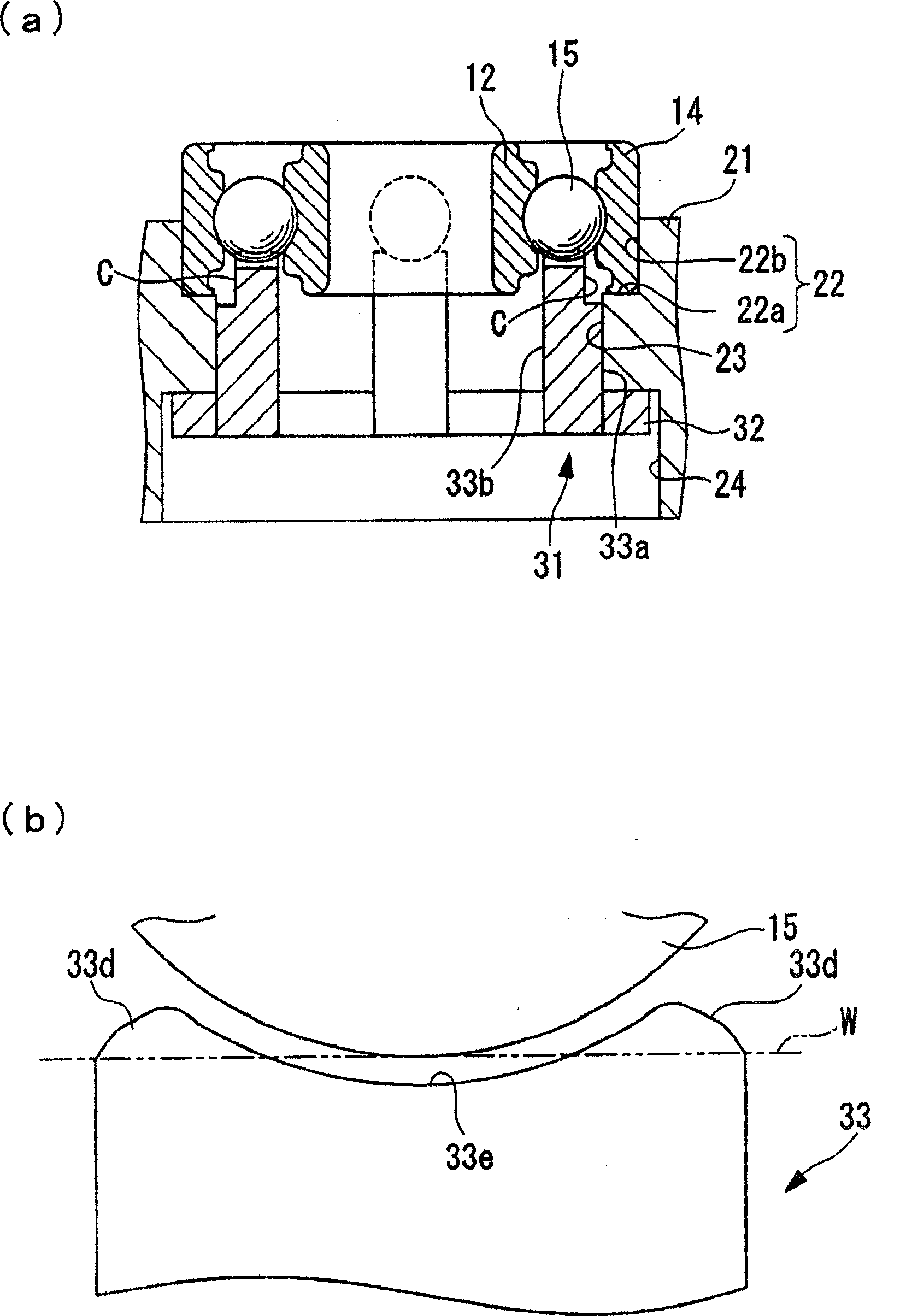
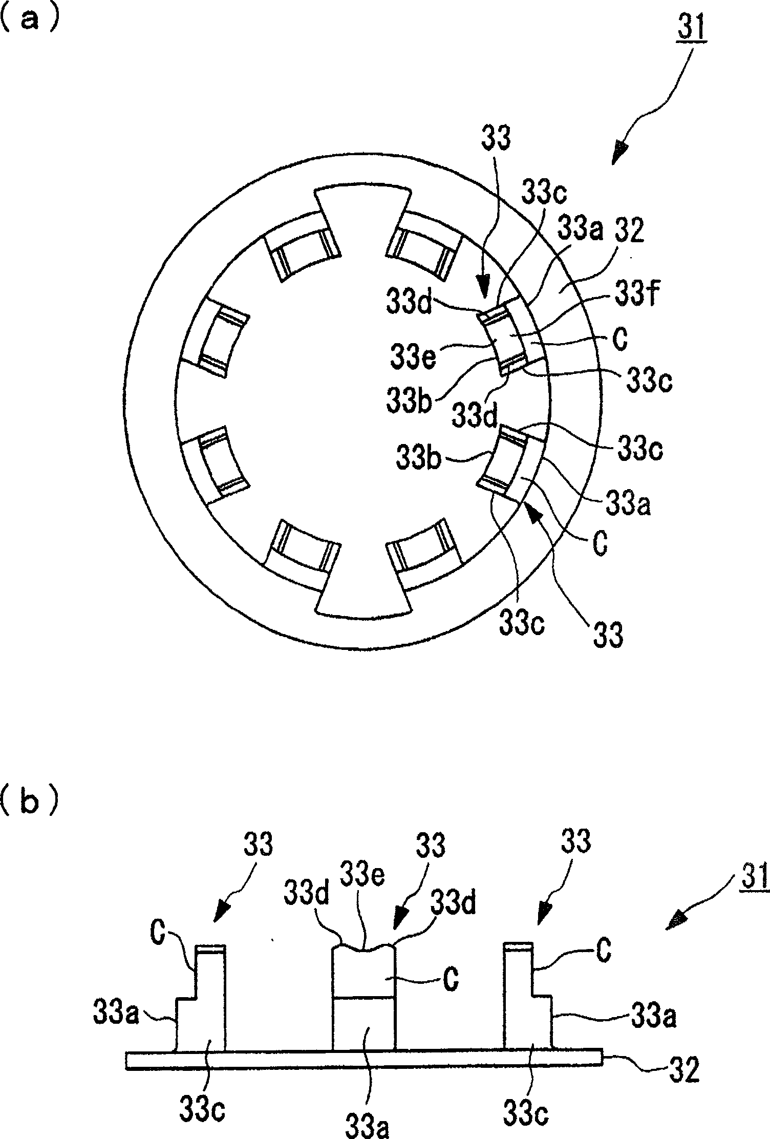
[0045] Hereinafter, embodiments of the present invention will be described with reference to the drawings.

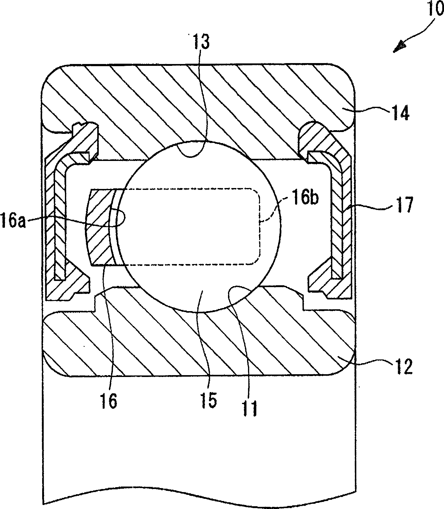
[0046] First, use figure 1 , the structure of the ball bearing 1 manufactured by the ball bearing manufacturing apparatus of this embodiment will be described.

[0047] The ball bearing 10 has a configuration in which a plurality of balls 15 are held by cages 16 at substantially equal intervals between the inner ring 12 and the outer ring 14, and a lubricant is filled between the inner ring 12 and the outer ring 14. In such a state, the axial ends of the inner and outer rings 12 are respectively sealed by the sealing member 17, wherein the inner ring 12 has an inner ring raceway surface 11 on the outer peripheral surface. The outer ring 13 has an outer ring raceway surface 13 on the inner peripheral surface. In the present embodiment, the ball bearing 10 has an outer diameter of about 30 mm to 40 mm and has eight balls 15 incorporated therein.

[0048] The retainer ...


PUM


Abstract

PROBLEM TO BE SOLVED: To provide a ball bearing manufacturing device and ball bearing manufacturing method capable of preventing its tool from wearing while a retainer is made practicable to be installed properly. SOLUTION: As a ball restricting tool to receive balls 15 of a ball bearing, a second ball restricting tool is provided in which a plurality of second supporting parts are arranged approximately at a constant spacing on one circumference in the condition that a gap is reserved in between. The side faces of the second supporting parts 46 facing the adjoining second supporting parts 46 are made receptacle surfaces 46a consisting each of a plumb surface. At the top of each second supporting part 46, a guide surface 46b is formed to guide balls 15 to between the receptacle surfaces 46a of the second supporting part 46 when inserted to between the inner ring and the outer ring, and in the condition that the second ball restricting tool is inserted between the inner ring and the outer ring of the ball bearing, the balls 15 are accepted between the adjoining second supporting parts 46 and received being pinched by their receptacle surfaces 46a. COPYRIGHT: (C)2006,JPO&NCIPI

Description

technical field [0001] The present invention relates to a ball bearing manufacturing device and a ball bearing manufacturing method. Background technique [0002] A ball bearing is a component in which a plurality of balls are arranged as rolling elements between the inner ring and the outer ring, and the balls are spaced at equal intervals by a cage made of resin or light metal between the inner ring and the outer ring. Configure and keep it. For example, it is used to support a rotating shaft or a drive shaft in casters, roller skates, or a spindle motor for HDD (Hard Disk Drive). [0003] As a method of manufacturing such a ball bearing, for example, a method of assembling a crown cage for a ball bearing to a bearing described in Patent Document 1 described later is known. [0004] According to this manufacturing method, a crown-shaped cage having a pocket opening for holding the rolling elements at one end in the axial direction is used as the cage. Then, a ring-shape...

Claims


Application Information

Patent Timeline
Patent Type & Authority Patents(China)
IPC IPC(8): F16C33/64F16C43/04F16C43/06
CPCF16C2300/02
Inventor 小林大介
Owner SEIKO INSTR INC
Learn More