Unlock instant, AI-driven research and patent intelligence for your innovation.

Apparatus for cleaning chamber using gas separation type showerhead

A technology for gas separation and cleaning chambers, applied in gaseous chemical plating, erecting/assembling bridges, bridge forms, etc.

Inactive Publication Date: 2009-07-22
WONIK IPS CO LTD
View PDF2 Cites 1 Cited by
  • Summary
  • Abstract
  • Description
  • Claims
  • Application Information

AI Technical Summary

Problems solved by technology

[0009] However, in conventional methods, since nitric oxide gas (NO) which has the greatest influence on cleaning efficiency is in the form of NO radicals rather than nitrogen (N) radicals or oxygen The form of (O) group is provided into the chamber, so there is a certain limitation in improving the cleaning efficiency by increasing the added gas

Method used


Image

  • Apparatus for cleaning chamber using gas separation type showerhead
  • Apparatus for cleaning chamber using gas separation type showerhead
  • Apparatus for cleaning chamber using gas separation type showerhead

Examples


Embodiment Construction

[0027] Preferred embodiments of the present invention will now be described in detail with reference to the accompanying drawings.

[0028] In the present invention, a gas separation type shower head is mainly used.

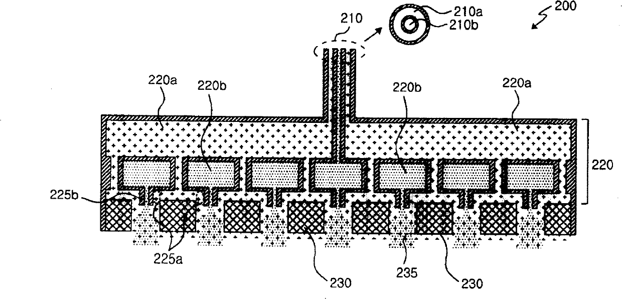
[0029] figure 2 One example of the gas separation type shower head used in the present invention is shown. figure 2 The illustrated gas separation type showerhead 200 includes a gas supply module 210 , a gas separation module 220 and a gas injection module 230 .

[0030] The first and second gases A and B are separately supplied through the gas supply module 210 . In order to separately supply the first and second gases A and B, the gas supply module 210 includes outer and inner supply pipes 210a and 210b separated from each other. refer to figure 2 , the first gas A is supplied to the outer supply pipe 210a, and the second gas B is supplied to the inner supply pipe 210b.

[0031] The first and second gases A and B supplied from the gas supply module 210 ...


PUM


Abstract

An apparatus for cleaning an inside of a chamber using a gas separation type showerhead is provided. The apparatus includes: a gas supply module through which first and second gases are separately supplied; a gas separation module through which the first and second gases are separately dispersed; and a gas injection module that includes a plurality of holes through which the separately dispersed first and second gases are commonly injected into the chamber, wherein at least one gas of the first and second gases includes an ionized first cleaning gas including a gas containing fluorine (F) ingredient, and wherein at least one gas of the first and second gases includes a non-ionized second cleaning gas including nitrogen oxide based gas (NxOy, x and y are integers equal to or more than 1).

Description

[0001] Background of the invention technical field [0002] The present invention relates to a device for cleaning a chamber, and more particularly to a device for cleaning a chamber using a gas separation shower head in which a cleaning gas containing an ionized fluorine (F) component is combined with a non-ionized nitrogen-oxygen-based cleaning Gas is used as cleaning gas. Background technique [0003] In a conventional method of cleaning the chamber, the cleaning gas flows from the top to the bottom of the chamber due to the top-down showerhead and chamber structure. Therefore, the total time to clean the chamber increases due to the reduced cleaning efficiency of the upper portion of the chamber. In addition, productivity decreases due to the use of more purge gas. [0004] For example, to clean the interior of a CVD chamber, for example CF 4 、C 2 f 6 、C 3 f 8 、C 4 f 8 and SF 6 etc. perfluoride-based cleaning gas (hereinafter referred to as PFC) and oxygen (O ...

Claims


Application Information

Patent Timeline
IPC IPC(8): C23C16/00
CPCE01D2/00E01D15/12E01D21/00
Inventor 裵根鹤金京洙金昊植尹荣培金德珍李来应
Owner WONIK IPS CO LTD