Functional filter felt for eliminating harmful constituents of fume, preparation method and application method thereof
A technology of harmful components and filter felt, which is applied in the field of flue gas purification, can solve the problems of short service life, insufficient desulfurization depth, and low sulfur capacity of activated carbon, and achieve the effects of low cost, simple structure, and long service life
- Summary
- Abstract
- Description
- Claims
- Application Information
AI Technical Summary
Problems solved by technology
Method used
Image
Examples
Embodiment 1
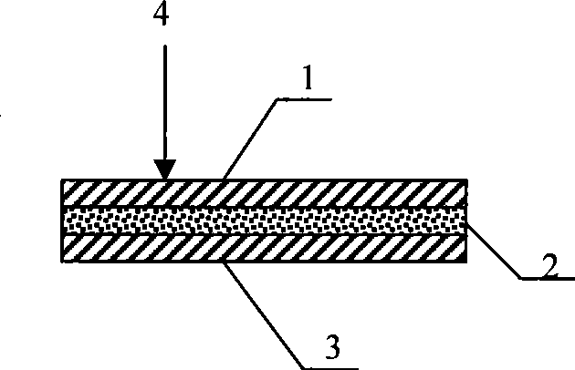
[0072] Such as figure 1 As shown in the cross-sectional diagram of the material, the structure of the functional filter felt from the surface to the inside is: PPS fiber layer 1, functional catalyst layer 2, PPS fiber layer 3, and 4 is the flow direction of the flue gas to be passed. Filter felts can be prepared using existing technologies such as polymer extrusion. The PPS polymer forms a loose fiber layer after melt blown spinning, and the catalyst particles are evenly sprayed on the loose fiber layer to form a catalyst layer with a certain thickness, and a loose PPS fiber layer is covered on it. , PPS fiber net is formed by rolling treatment, and then the overall structure of the filter felt is reinforced by acupuncture treatment. Both PPS fiber layer 1 and PPS fiber layer 3 have a thickness of 0.8mm and a weight of 250g / m 2 . The functional catalyst layer 2 is supported by one or more of noble metals and metal oxides on zeolites, TiO 2 , ZrO 2 、Al 2 o 3 , SiO 2 、Ge...
Embodiment 2
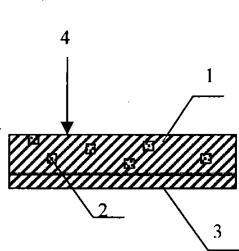
[0074] Such as figure 2 As shown in the cross-sectional diagram of the material, the structure of the functional filter felt from the surface to the inside is: PPS fiber composite layer 1, PPS fiber layer 3, PPS fiber composite layer 1 is composed of PPS fiber and functional catalyst 2, and 4 is to be direction of flue gas flow. The PPS polymer is heated and melted, extruded and melt-blown, and the catalyst particles are evenly sprayed onto the polymer fibers while the polymer fibers are cooled and spread to ensure that the catalyst particles are evenly dispersed and not agglomerated. . After cooling into fibers, a layer of loose PPS fiber layer is covered on it, and the PPS fiber net is formed by rolling, and then the overall structure of the filter felt is reinforced by needle punching. PPS fiber composite layer 1 has a thickness of 2.5mm and a weight of 850g / m 2 , the thickness of PPS fiber layer 3 is 1mm, and the weight is 300g / m 2 . Functional catalyst 2 is supporte...
Embodiment 3
[0077] Such as figure 2 As shown in the cross-sectional diagram of the material, the structure of the functional filter felt from the surface to the inside is: PPS fiber composite layer 1, PPS fiber layer 3. The PPS fibers used in the PPS fiber composite layer 1 and the PPS fiber layer are modified PPS fibers processed by plasma surface modification, and the preparation method of the filter felt is as in Example 2, and the functional catalyst content is calculated on the basis of the filter felt weight 0.5wt%. Other structural parameters of the filter felt and its flue gas purification method are the same as those in Example 2.
PUM
| Property | Measurement | Unit |
|---|---|---|
| Thickness | aaaaa | aaaaa |
| Gram weight | aaaaa | aaaaa |
| Thickness | aaaaa | aaaaa |
Abstract
Description
Claims
Application Information
 - R&D
- Intellectual Property
- Life Sciences
- Materials
- Tech Scout
- Unparalleled Data Quality
- Higher Quality Content
- 60% Fewer Hallucinations
Browse by: Latest US Patents, China's latest patents, Technical Efficacy Thesaurus, Application Domain, Technology Topic, Popular Technical Reports.
© 2025 PatSnap. All rights reserved.Legal|Privacy policy|Modern Slavery Act Transparency Statement|Sitemap|About US| Contact US: help@patsnap.com


