
Process and catalyst system for SCR of NOx

a catalyst system and catalyst technology, applied in the direction of metal/metal-oxide/metal-hydroxide catalysts, machines/engines, arsenic compounds, etc., can solve the problem of reducing the attractiveness of catalysts, reducing the efficiency of catalysts, etc. problem, to achieve the effect of stable performance and no tendency to deactivation

Active Publication Date: 2011-11-22
UMICORE AG & CO KG
View PDF7 Cites 83 Cited by
  • Summary
  • Abstract
  • Description
  • Claims
  • Application Information

AI Technical Summary

Benefits of technology

The dual bed catalyst system achieves high NOx conversion across a broad temperature range with reduced hydrogen usage and increased resistance to deactivation, maintaining activity levels and minimizing hydrogen requirement even at low temperatures.

Problems solved by technology

The emission of nitrogen oxides by exhaust gases in stationary and automotive applications has long been a major environmental issue.
Conventional catalysts for NOx reduction comprise vanadium; however, these catalysts are becoming less and less attractive as tightening environmental regulations are expected to forbid their use.
This solution has some drawbacks: 1) The oxidation catalyst required for the NO oxidation requires a high loading of precious Pt; 2) The oxidation catalyst deactivates significantly over time resulting in a change in SCR activity which makes regulation of the NH3 / urea dosage difficult; 3) It is not possible to obtain the optimum NO:NO2 1:1 ratio in the whole operational temperature interval.
High SCR activity can be achieved over Cu-zeolite materials without taking advantage of the fast SCR reaction; however, Cu-zeolites are more prone to hydrothermal deactivation than Fe-zeolites, which limits their use in many applications.
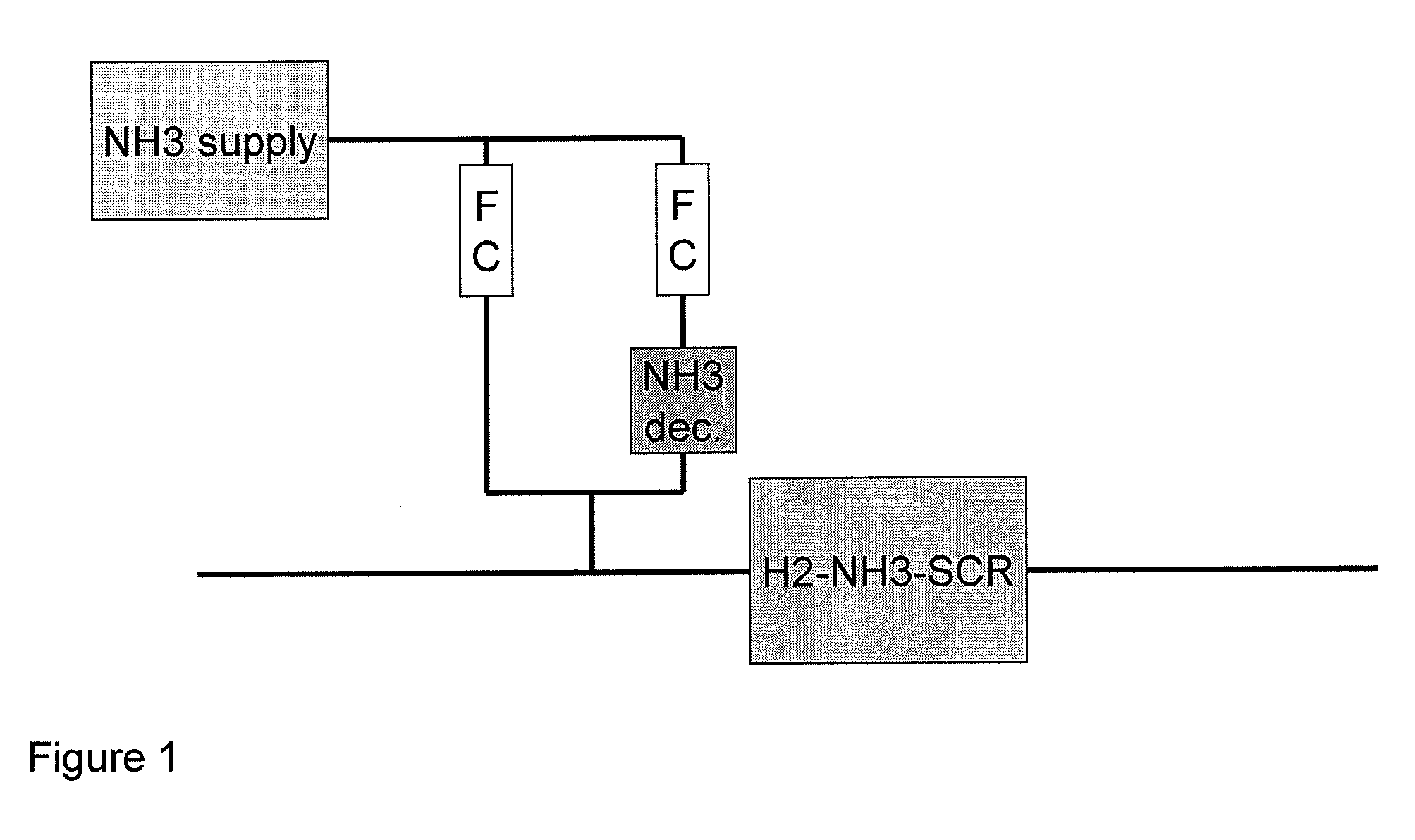
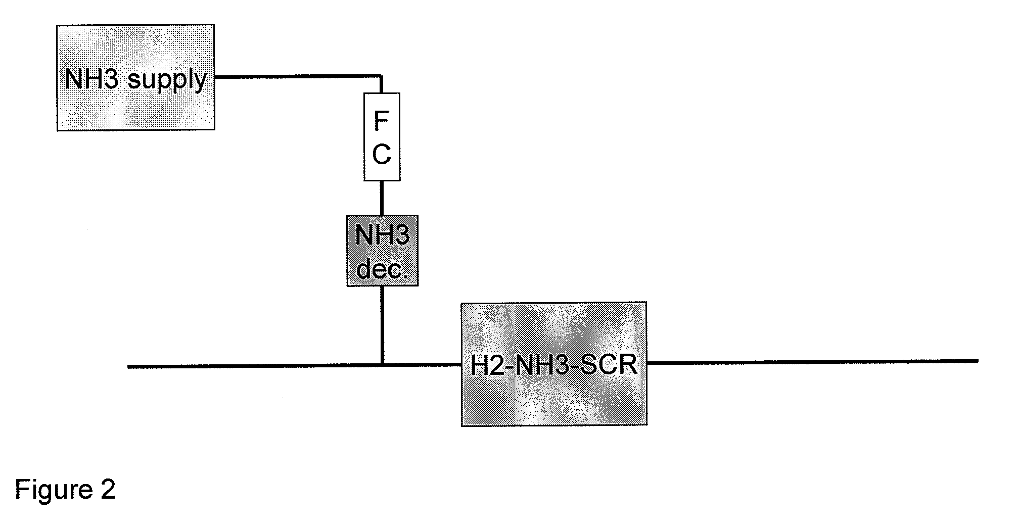
Our own studies on the performance of Ag / Al2O3 catalyst in H2-assisted SCR removal with ammonia (or urea) show that this catalyst in the presence of reasonable amount of hydrogen (1000 ppm) provides a very promising NOx conversion in the course of NH3-DeNOx of a gas with approximately 1:3:1 molar ratio of NH3:H2:NO within the low temperature range 175 to 250° C. However, in the absence of hydrogen, which is desired in order to keep costs down, the catalyst is not active in SCR removal with ammonia or urea Our studies on this catalyst also show that the reduction of 1 mole of NO requires a considerable amount of hydrogen, namely 1.5 to 2 moles of hydrogen.

Method used


Image

  • Process and catalyst system for SCR of NOx
  • Process and catalyst system for SCR of NOx
  • Process and catalyst system for SCR of NOx

Examples


example 1

Comparative

[0051]Experiments were conducted to evaluate the performance of 1% Ag—Al2O3 (1 wt %) in NH3-DeNOx upon changing H2 concentration from 100 to 1600 ppm. These experiments allow evaluation of the efficiency of overall NH3-DeNOx process with H2-coffeding in terms of the amount of H2 required for high NOx conversion.

[0052]The catalyst containing 1 wt % Ag / Al2O3 (SASOL 1, SBET=150 m2 / g) was prepared by incipient-wetness impregnation, where 3.0 g Al2O3 (SASOL N1) was loaded with 1 wt % Ag by incipient-wetness impregnation with a water solution of AgNO3 (2.2 ml) containing 0.014 g Ag / ml. The product was dried overnight at room temperature in air. The resulting material was calcined at 600° C. (4 h) in flowing air (−300 ml / min). The temperature was increased from room temperature to 600° C. at a rate of 0.5° C. / min.

[0053]The performance of 1% Ag—Al2O3 in NH3-DeNOx at different H2 concentrations is shown in FIG. 6, top part. Reaction conditions: GHSV=72 000 h−1, feed gas compositio...

example 2

Invention

[0057]The performance of layered Fe-beta-zeolite (commercial CP7124) and 1% Ag—Al2O3 (1 wt %) in NH3-DeNOx at different H2 concentrations was investigated. The amount of H2 added into the reaction mixture was changed from 100 ppm to 1600 ppm and the catalyst performance was evaluated at 100-550° C. Reaction conditions: Feed gas composition: 340 ppm NH3, 300 ppm NO, 100-1600 ppm H2, 7% O2, 4.5% H2O, 10% CO2 balance with N2. Overall flow rate: 500 ml / min. Catalyst load: 0.12 g Fe-beta-zeolite (front layer)+0.36 g 1% Ag / Al2O3 (downstream layer).

[0058]The layered catalyst consisted of a 0.12 g top layer (0.2 cm3) of Fe-beta-zeolite, fraction 0.4 to 1.0 mm and a 0.36 g bottom layer (0.5 cm3) of 1 wt % Ag / Al2O3 (SASOL 1).

[0059]The layered catalyst was prepared by incipient-wetness impregnation where 5.0 g Al2O3 (SASOL N1) was loaded with 1 wt % Ag by incipient-wetness impregnation with a water solution of AgNO3 (3.7 ml) containing 0.014 g Ag / ml. The product was dried overnight at...

example 3

[0065]The performance of simply mechanically mixing Fe-beta-zeolite with Ag / Al2O3 was compared with the dual bed Fe-beta-zeolite with Ag / Al2O3, in which there is spatial separation of both catalysts, with Fe-beta-zeolite as a front part of the catalyst.

[0066]Mechanically mixed catalyst system: 0.31 g (0.5 cm3) of 1 wt % Ag / Al2O3 (Boehmite)—prepared as described below—was mixed with 0.12 g (0.2 cm3) of Fe-beta-zeolite (CP 7124), thoroughly crushed to powder and pressed fraction of 0.4 to 1.0 mm. The 1 wt % Ag / Al2O3 (Boehmite) was prepared by incipient-wetness impregnation where 3.0 g of Boehmite was loaded with 1 wt % Ag by incipient-wetness impregnation with a water solution of AgNO3 (2.2 ml), containing 0.014 g Ag / ml. The product was dried overnight at room temperature in air and the resulting material was calcined at 600° C. (4 h) in flowing air (−300 ml / min). The temperature was increased from room temperature to 600° C. at a rate of 0.5° C. / min. The resulting catalyst compositio...


PUM

PropertyMeasurementUnit
temperaturesaaaaaaaaaa

Abstract

Process for reducing nitrogen oxides to nitrogen in an exhaust gas comprising passing the exhaust gas in the presence of a reducing agent through a catalyst system comprising at least two catalyst beds, in which a first catalyst bed is an iron-beta-zeolite and a second catalyst bed downstream is silver supported on alumina.

Description

BACKGROUND OF THE INVENTION[0001]1. Field of the Invention[0002]The present invention concerns a process and catalyst system for reduction of nitrogen oxides from exhaust gases using a reducing agent such as ammonia and urea. In particular, the invention relates to a dual bed catalyst system for reduction of nitrogen oxides using a reducing agent in which the first catalyst bed is an iron-beta-zeolite (Fe-beta-zeolite) and the second catalyst bed downstream is silver supported on alumina (Ag / Al2O3). More particularly, the present invention relates to a process and catalyst system for converting NOx in exhaust gas from lean-burn combustion engines to nitrogen by adding a mixture of hydrogen and ammonia to the exhaust gas and subsequently passing the gas over a suitable dual bed catalyst, in which the first catalyst bed is an iron-beta-zeolite (Fe-beta-zeolite) and the second catalyst bed downstream is silver supported on alumina (Ag / Al2O3).[0003]2. Description of the Related Art[0004...

Claims


Application Information

Patent Timeline
Patent Type & Authority Patents(United States)
IPC IPC(8): B01D53/56B01D53/94F01N3/10
CPCB01D53/9418B01J23/50B01J29/7615B01J35/0006F01N3/2066Y02T10/24B01D2251/202B01D2251/2062B01D2255/104B01D2255/20738B01D2255/502B01D2258/012B01J35/04B01J37/0201F01N2610/02B01D53/9477Y02T10/12B01J35/19B01J35/56B01D53/56F01N3/10
Inventor STAKHEV, ALEXANDRDAHL, SORENGEKAS, IOANNISGABRIELSSON, PAR L. T.
Owner UMICORE AG & CO KG
Learn More