Panel for liquid crystal display

A liquid crystal display, panel technology, applied in static indicators, instruments, transistors, etc., can solve the problems of affecting cutting and manufacturing difficulty, and achieve the effect of reducing space constraints and reducing coating difficulty

Inactive Publication Date: 2009-07-22
INNOCOM TECH (SHENZHEN) CO LTD +1
View PDF5 Cites 2 Cited by
  • Summary
  • Abstract
  • Description
  • Claims
  • Application Information

AI Technical Summary

Problems solved by technology

[0008] In order to solve the above-mentioned problems affecting cutting and manufacturing difficulty, it is necessary to provide a panel for liquid crystal displays that has little effect on cutting and reduces manufacturing difficulty

Method used


Image

  • Panel for liquid crystal display
  • Panel for liquid crystal display
  • Panel for liquid crystal display

Examples


Embodiment Construction

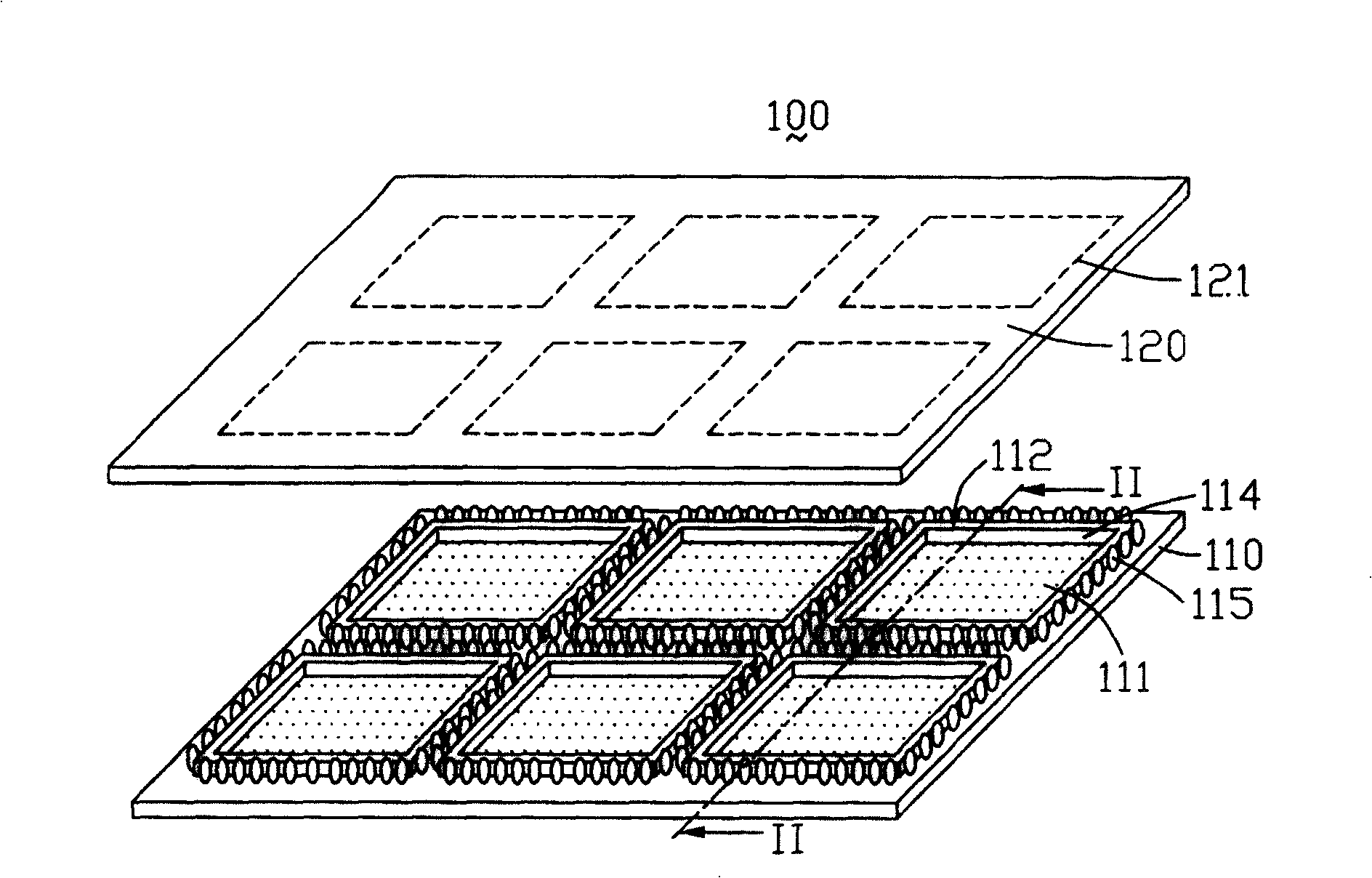
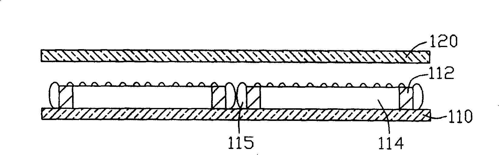
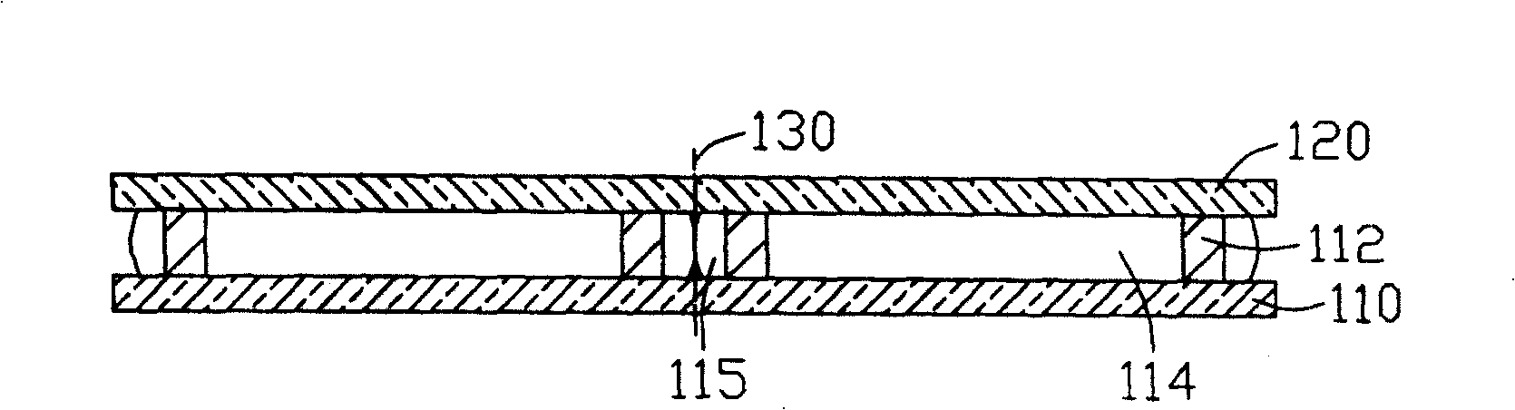
[0022] Please also refer to Figure 4 , Figure 5 and Figure 6 , Figure 4 is an exploded schematic view of the panel of the present invention for liquid crystal display, Figure 5 yes Figure 4 A schematic diagram of coating frame glue on a mother substrate of the panel shown, Figure 6 yes Figure 4 The schematic cross-section along the VI-VI direction in . The panel 200 for a liquid crystal display includes a first mother substrate 210 , a second mother substrate 220 , sealant 230 and conductive adhesive dots 240 . The second mother substrate 220 is disposed opposite to the first mother substrate 210 , and the sealant 230 and conductive adhesive dots 240 are disposed between the first mother substrate 210 and the second mother substrate 220 .

[0023] A plurality of TFT substrates 211 are formed on the first mother substrate 210 , and a plurality of color filter substrates 221 are formed on the second mother substrate 220 . Each thin film transistor substrate 211 i...


PUM


Abstract

A face plate used on liquid crystal display is prepared for setting the first and the second mother base plates in opposite way, arranging multiple glue line between two said mother base plates, utilizing said glue lines and two said mother base plates to define out multiple containing space, setting at least one top-bottom through containing space in each glue line and laying conduction resin in said containing space.

Description

【Technical field】 [0001] The invention relates to a panel for a liquid crystal display. 【Background technique】 [0002] At present, liquid crystal displays are gradually replacing traditional cathode ray tube (Cathode Ray Tube, CRT) displays used in calculators, and because liquid crystal displays are light, thin, and small, they are very suitable for use in desktop computers, laptops, etc. In computer, personal digital assistant (Personal Digital Assistant, PDA), portable phone, TV and various office automation and audio-visual equipment. The liquid crystal panel is its main component. The liquid crystal panel generally includes a thin film transistor substrate, a color filter substrate and a liquid crystal layer sandwiched between the thin film transistor substrate and the color filter substrate. In addition, a common electrode and a pixel electrode are formed on the color filter substrate and the thin film transistor substrate facing each other so as to apply an electric...

Claims


Application Information

Patent Timeline
Patent Type & Authority Patents(China)
IPC IPC(8): G02F1/133G02F1/136H01L29/786
Inventor 吴佳怡萧坤星
Owner INNOCOM TECH (SHENZHEN) CO LTD
Why Eureka
Try Eureka