Power conversion system

A technology for converting system and power, which is applied in the direction of output power conversion device, control system, irreversible DC power input to AC power output, etc., to achieve the effect of miniaturization, reduction and suppression of voltage fluctuations

Inactive Publication Date: 2009-07-22
HITACHI LTD
View PDF8 Cites 0 Cited by
  • Summary
  • Abstract
  • Description
  • Claims
  • Application Information

AI Technical Summary

Problems solved by technology

In the prior art described above, the PWM carriers on the rectifier side and the inverter side are the same, but since there is a pulse waveform difference between the rectifier side and the inverter side, when the phase difference of the PWM carrier is 0, the capacitor The current does not necessarily have a minimum value, so there is a problem that it is necessary to further suppress the current flowing into the smoothing capacitor

Method used


Image

  • Power conversion system
  • Power conversion system
  • Power conversion system

Examples


Embodiment Construction

[0021]

The power conversion system of the present invention will be described in detail below based on the illustrated embodiments.

[0022]

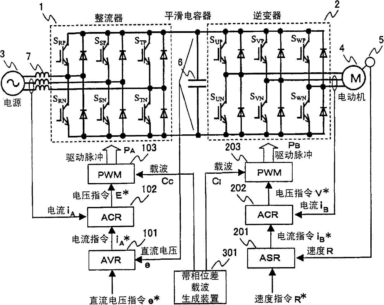
Fig. 1 shows an embodiment of the present invention, in the figure, 301 represents the generator with phase difference carrier, can generate the carrier CC with triangular waveform and the triangular waveform with certain phase difference Δ with respect to this carrier CC by this carrier generator There are two types of carriers, namely carrier CI, and these carriers can be supplied to PWM103 and PWM203, respectively. In addition, other structures are the same as those of the power conversion system in the prior art shown in FIG. 8 and FIG. 9 .

[0023]

Also, in the embodiment shown in FIG. 1 , the voltage across the terminals of the smoothing capacitor 6 is firstly fed back as a DC voltage e on the rectifier 1 side, and the current command iA* on the power supply side is generated by the AVR 101 so that the DC voltage e and DC The vo...


PUM


Abstract

PROBLEM TO BE SOLVED: To provide a power conversion system capable of minimizing the capacity of a smoothing capacitor in a DC intermediate circuit. ŽSOLUTION: This power conversion system, having the smoothing capacitor 6 between a converter 1 and an inverter 2, includes a carrier generator 301 with a phase difference and is set with a predetermined phase difference Δ between a carrier C<SB>C< / SB>for PWM controlling the converter 1 and a carrier C<SB>I< / SB>for PWM controlling the inverter 2 to reduce the magnitude of a current flowing through the smoothing capacitor 6 by adjusting the phase difference Δ, thus minimizing the capacitance of the smoothing capacitor 6. Ž

Description

technical field [0001] The present invention relates to a power conversion system having a DC voltage smoothing capacitor between a rectifier part and an inverter part, and more particularly to a power conversion system in which the rectifier part and the inverter part operate in a pulse width modulation manner. Background technique [0002] In recent years, in the control of AC motors typified by induction motors and synchronous motors, variable-frequency variable-voltage power conversion systems called VVVF inverters and the like have begun to be used. In this case, a power conversion system in which a rectifier part (converter) and an inverter part (inverter) are connected via a DC circuit is generally used. [0003] Furthermore, as shown in FIG. 8, in the above-mentioned power conversion system, for example, an alternating current (three-phase alternating current) supplied from a commercial power supply or the like is converted into direct current (direct current) by ...

Claims


Application Information

Patent Timeline
Patent Type & Authority Patents(China)
IPC IPC(8): H02M7/48H02M1/14H02P27/08
Inventor 大和育男稻叶博美
Owner HITACHI LTD
Why Eureka
Try Eureka