
Internal combustion engine device

A technology of internal combustion engine and fuel oil, which is applied in the direction of fuel injection device, starting device with mechanical power storage, charging system, etc. It can solve problems such as failure and electronic device failure, and achieve the effect of simple design scheme

Inactive Publication Date: 2009-07-29
MAN B & W DIESEL AS
View PDF3 Cites 0 Cited by
  • Summary
  • Abstract
  • Description
  • Claims
  • Application Information

AI Technical Summary

Problems solved by technology

Especially for devices used to drive sailing, the failure of this device has serious consequences, since the ship can only control it while sailing
But for internal combustion engine installations used on land, electronic failures can also lead to bad consequences

Method used


Image

  • Internal combustion engine device
  • Internal combustion engine device
  • Internal combustion engine device

Examples


Embodiment Construction

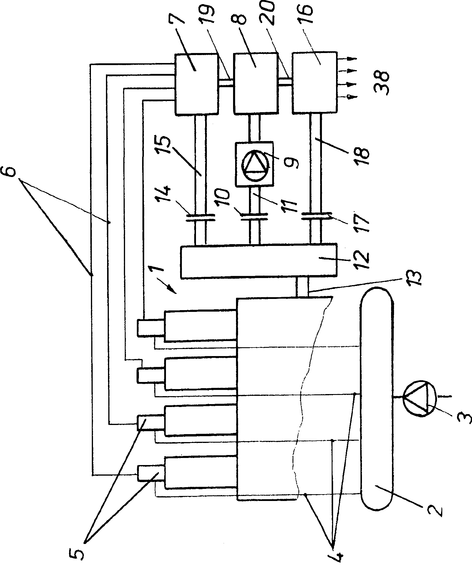
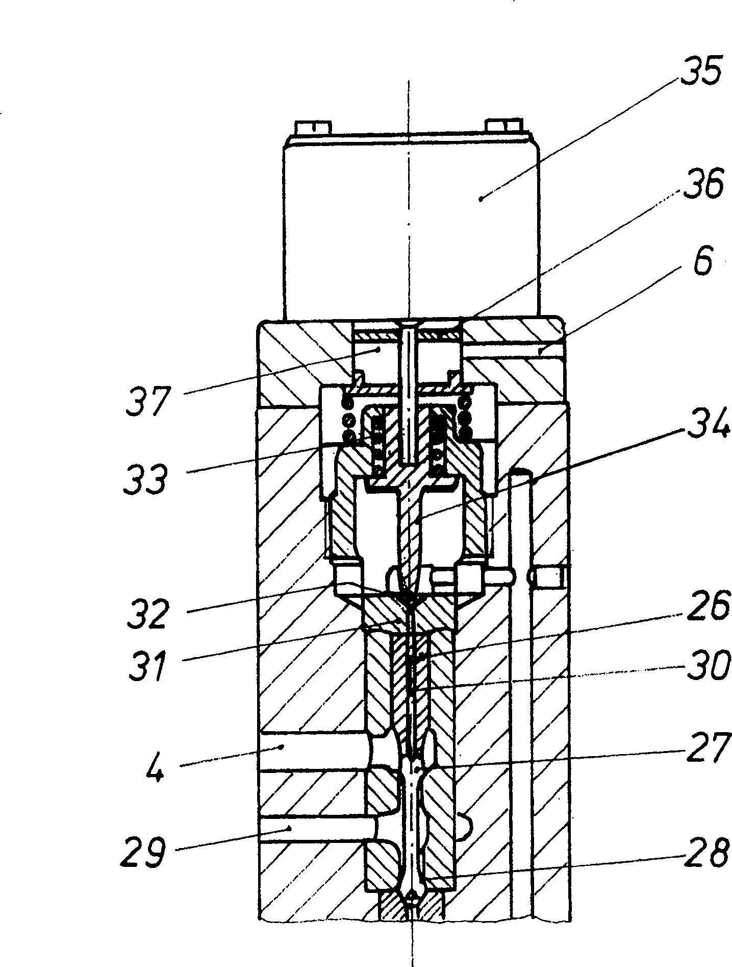
[0011] figure 1 The cylinder of the internal combustion engine is designated overall with 1 and the pressure accumulator line with 2 . The pressure accumulator line 2 is supplied with fuel under high pressure by means of a pump 3 . The fuel then passes through fuel lines 4 to fuel valves 5 which are each assigned to a cylinder. In the illustrated exemplary embodiment, the internal combustion engine has four cylinders 1 . However, the present invention is not limited to a certain number of cylinders.

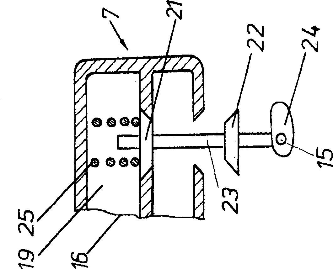
[0012] Each fuel valve 5 is connected to a compressed fluid reservoir 8 via a compressed fluid line 6 and a control unit 7 . Compressed air is used as the compressed fluid in the illustrated embodiment. A pump 9 feeding a compressed fluid reservoir 8 is connected via a shaft 11 accommodating a separating clutch 10 to a transmission 12 which can be driven by a crankshaft 13 of the internal combustion engine. However, it is also possible to drive the pump 9 via an electric mot...


PUM


Abstract

The internal combustion engine plant has a pressure accumulator line (2) holding fuel at high pressure and from which branches a fuel line (4) to each cylinder (1). The fuel line accommodates an electronically controlled fuel valve (5), with each valve alternately pressurized by compressed air for opening. A compressed air valve controlled in dependence upon the position of the engine's crankshaft (13) is installed in a compressed air line (6) between a compressed air accumulator (8) and each fuel valve. An independent claim is included for a fuel valve for an internal combustion engine plant.

Description

technical field [0001] The invention relates to an internal combustion engine arrangement having a pressure accumulator line which absorbs fuel under high pressure, from which pressure accumulator line extends to each cylinder a fuel line accommodating an electrically controlled fuel valve. Background technique [0002] If the electronic system for controlling the fuel valve in such an internal combustion engine arrangement fails, the internal combustion engine stops running. Especially for devices used to drive sailing, failure of this device has serious consequences, since the vessel can only control it while sailing. However, failure of the electronics also leads to unfavorable consequences for internal combustion engine installations used on land. Contents of the invention [0003] It is therefore the object of the present invention to design an internal combustion engine arrangement such that in the event of a failure of the electronic system the internal combustion ...

Claims


Application Information

Patent Timeline
Patent Type & Authority Patents(China)
IPC IPC(8): F02M67/02F02M67/12F02M61/14F02N9/04F02M47/00F02MF02M47/02F02M47/04F02M63/00F02M63/02
CPCF02M63/0015F02M63/004F02M63/0005F02M47/046F02M63/0045F02M63/0225A61L2/16A61L9/01
Inventor U·延斯R·雷特
Owner MAN B & W DIESEL AS
Learn More