Channel disk coupler for airflow rotary cup spinning appts.

A technology of rotor spinning and splicer, which is applied to spinning machines, open-end spinning machines, continuous winding spinning machines, etc., can solve the problems of high cost and high manufacturing cost, and achieve convenient replacement and economical production cost. , the effect of precise centering

Inactive Publication Date: 2009-08-12
SAURER GERMANY GMBH & CO KG
View PDF9 Cites 0 Cited by
  • Summary
  • Abstract
  • Description
  • Claims
  • Application Information

AI Technical Summary

Problems solved by technology

[0016] The device known for example from DE 37 29 425 A1 is relatively expensive due to its various parts
That is to say, the manufacturing cost of this kind of channel disc adapter is relatively high

Method used


Image

  • Channel disk coupler for airflow rotary cup spinning appts.
  • Channel disk coupler for airflow rotary cup spinning appts.
  • Channel disk coupler for airflow rotary cup spinning appts.

Examples


Embodiment Construction

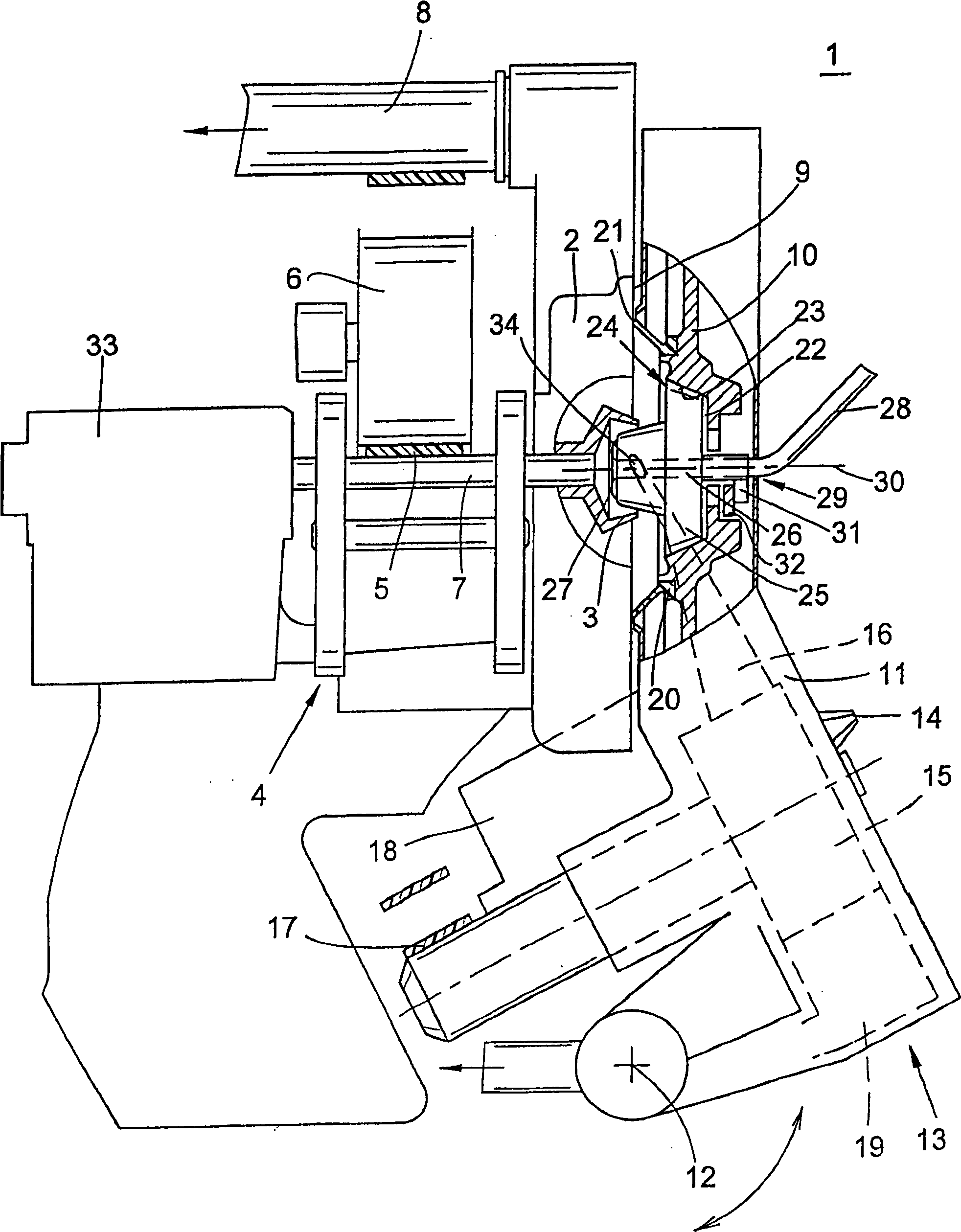
[0037] figure 1 It shows a side view of an air rotor spinning device 1 with a rotor housing 2 under vacuum in which a rotor 3 rotates at a high speed. The rotor 3 is supported by its rotor shaft 7 on a double disc bearing 4 in a known manner; the axial positioning of the rotor 3 is accomplished by a thrust bearing 33 .

[0038] As is known, the rotor 3 is driven by means of a machine-length tangential belt 5 which presses a pressure roller 6 against the rotor shaft 7 .

[0039] In order to generate the required spinning vacuum, the rotor housing 2 is connected via a vacuum line 8 to a source of vacuum (not shown).

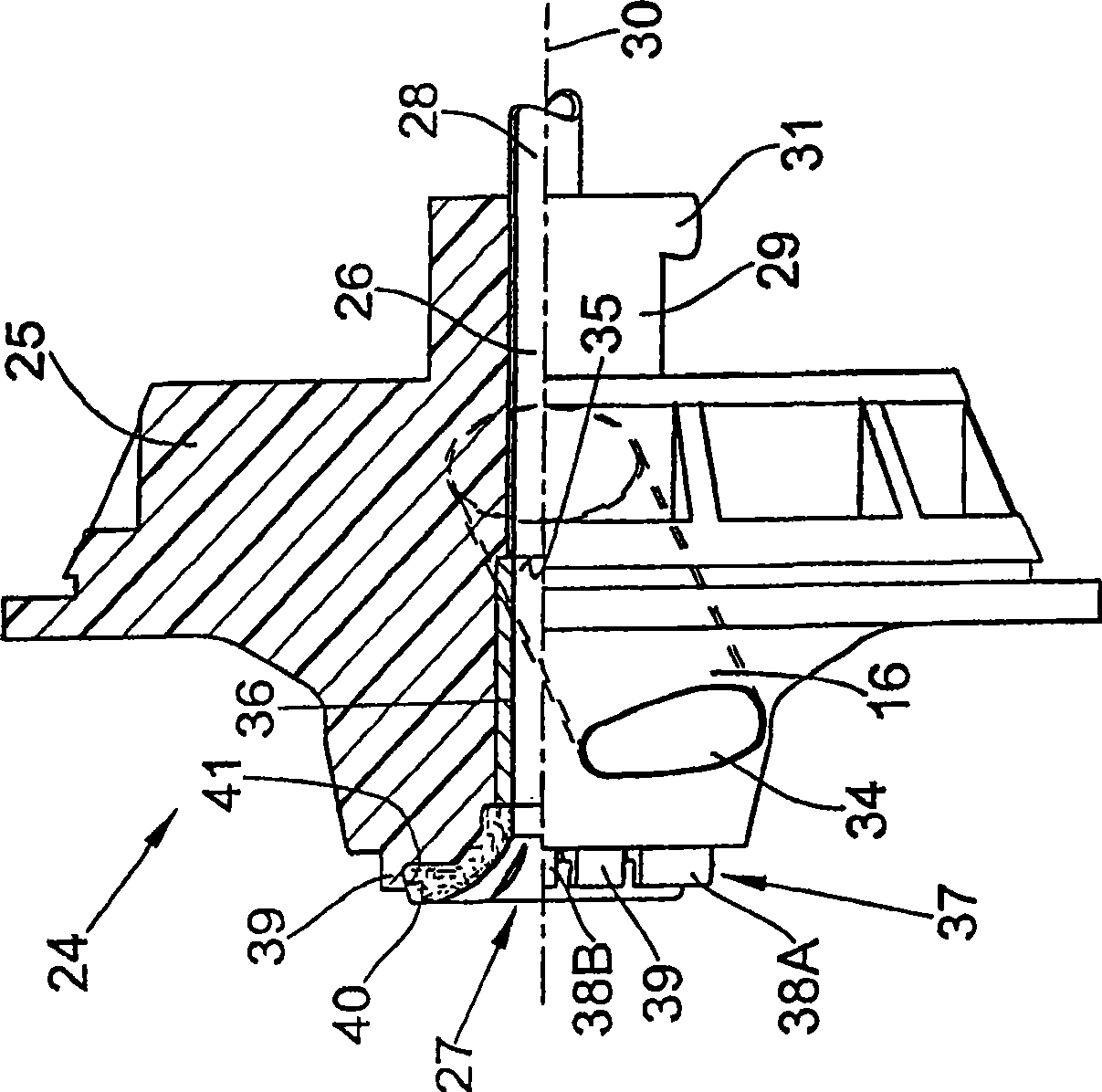
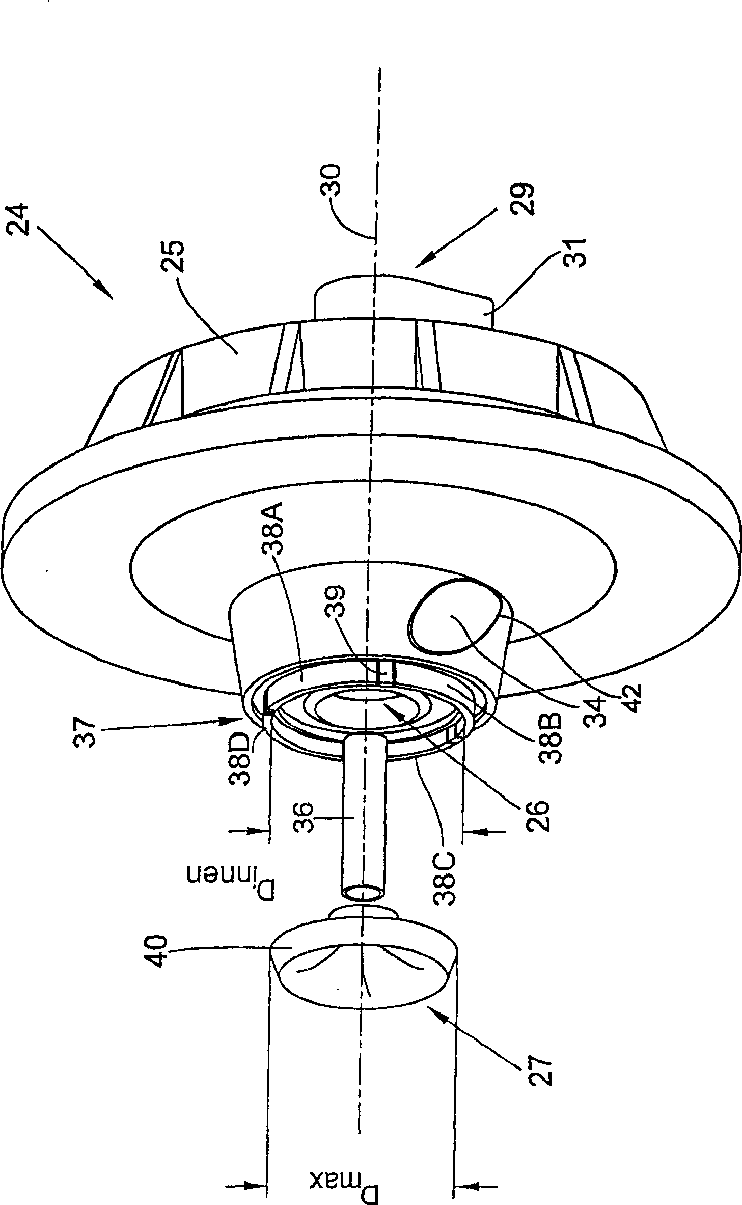
[0040] The running surface 9 of the rotor housing 2 is closed by a so-called fiber channel disk 10 , which is designed as a cover part of the rotor housing 11 .

[0041] The fiber channel disc 10 is either used as a component of the rotating cover 11 or detachably fixed on the rotating cover 11 .

[0042] Such as figure 1 As shown, other components of the air-f...


PUM


Abstract

The invention relates to a channel disc adapter for an air rotor spinning device. The air rotor spinning device has a rotor rotating at a high speed in an evacuable rotor housing, here with a channel disc adapter made of plastic, with a nozzle area for the fiber channel and a The central channel hole of the yarn navel is replaceably mounted in the support of a fiber channel disc which seals the rotor housing when spinning is in motion. According to the arrangement of the invention, the channel disc adapter (24) has an integrally formed clamping connector (37) in the entry area of ​​the channel hole (26) for centering and fixing of the yarn navel (27).

Description

technical field [0001] The invention relates to a channel disc adapter for an air rotor spinning device. The air rotor spinning device has a rotor rotating at high speeds in an evacuable rotor housing, here with a channel disc adapter made of plastic, with a nozzle area for the fiber guide channel and a The central channel hole of the yarn navel is replaceably mounted in the support of a fiber channel disc, which seals the rotor housing during spinning operation. Background technique [0002] Known air rotor spinning devices are equipped with an exchangeable channel disc adapter in the region of their fiber channel discs, as described in detail in DE 43 34 485 A1, for example. [0003] When this air-flow rotor spinning device is spinning, a high-speed rotor rotates in a vacuumed rotor housing. Here the rotor cup housing is sealed by a rotatable cover, and the fiber sliver carding device of the spinning device is integrated in the cover. [0004] That is to say, the runnin...

Claims


Application Information

Patent Timeline
Patent Type & Authority Patents(China)
IPC IPC(8): D01H4/08D01H4/38D01H4/40
CPCD01H4/40D01H4/38
Inventor H·-G·瓦森霍文
Owner SAURER GERMANY GMBH & CO KG
Why Eureka
Try Eureka