Unlock instant, AI-driven research and patent intelligence for your innovation.

High efficient mixer

A technology for mixers and reducers, which is applied to mixers, mixers with rotating stirring devices, and dissolution, etc. It can solve the problems of non-continuous production, dead ends, and high energy consumption, and achieves fast mixing speed, convenient cleaning, and well mixed effect

Inactive Publication Date: 2009-08-19
耐驰(上海)机械仪器有限公司
View PDF5 Cites 0 Cited by
  • Summary
  • Abstract
  • Description
  • Claims
  • Application Information

AI Technical Summary

Problems solved by technology

The mixers currently on the market are generally spiral, ribbon, paddle, etc., and their disadvantages are: no continuous production, large footprint, dead ends, high energy consumption, uneven mixing, and long mixing time

Method used


Image

  • High efficient mixer
  • High efficient mixer
  • High efficient mixer

Examples


Embodiment 1

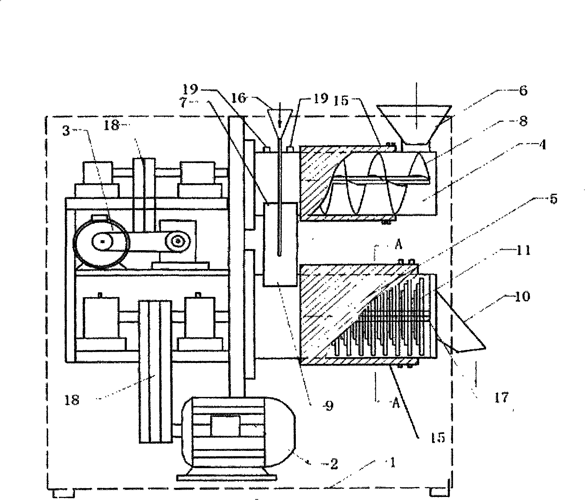
[0024] Such as figure 1 and figure 2 As shown, the present invention includes a housing 1, a motor 2, a speed reducer 3, a conveying mechanism 4 and a mixing mechanism 5, the conveying mechanism 4 is provided with a feed inlet 6, an outlet 7, and a screw conveying blade 8 is provided in it, and the mixing mechanism 5 An inlet 9 and a discharge port 10 are provided. The conveying mechanism 4 and the mixing mechanism 5 are both barrel-shaped. The inlet 9 of the mixing mechanism 5 is connected to the outlet 7 of the conveying mechanism 4. The mixing mechanism 5 is provided with a plurality of The mixing blade 11 is fixed on the rotating shaft 17 . The mixing blades 11 are in groups of 4 pieces, and the sharp angles of each mixing blade 11 form an angle of 45° in the horizontal plane with the adjacent sharp angles, forming an octagonal star shape. The rotating shaft 17 is provided with a long key pin 12 , and the inner hole of the mixing blade 11 has a key groove 13 matching wi...

Embodiment 2

[0026] Such as figure 1 , image 3 and Figure 4 As shown, the present invention includes a housing 1, a motor 2, a speed reducer 3, a conveying mechanism 4 and a mixing mechanism 5, the conveying mechanism 4 is provided with a feed inlet 6, an outlet 7, and a screw conveying blade 8 is provided in it, and the mixing mechanism 5 An inlet 9 and a discharge port 10 are provided. The conveying mechanism 4 and the mixing mechanism 5 are both barrel-shaped. The inlet 9 of the mixing mechanism 5 is connected to the outlet 7 of the conveying mechanism 4. The mixing mechanism 5 is provided with a plurality of The mixing blade 11 is fixed on the rotating shaft 17 . The mixing blades 11 are in groups of 4 pieces, and the sharp angles of each mixing blade 11 form an angle of 45° in the horizontal plane with the adjacent sharp angles, forming an octagonal star shape. The rotating shaft 17 is provided with 8 long key pins 12 equidistantly arranged at an arc angle of 45° along the cross ...


PUM


Abstract

The invention relates to the fields of plastics, pharmacy, fine chemical industry and food machinery, in particular to a high-speed mixer. It includes a housing (1), a motor (2), a reducer (3), a conveying mechanism (4) and a mixing mechanism (5), and the conveying mechanism (4) is provided with a feed inlet (6), an outlet (7 ), which is provided with a screw conveying blade (8), the mixing mechanism (5) is provided with an inlet (9), a discharge port (10), and the main bodies of the conveying mechanism (4) and the mixing mechanism (5) are drums shape, it is characterized in that the inlet (9) of the mixing mechanism (5) is connected to the outlet (7) of the conveying mechanism (4), and the mixing mechanism (5) is provided with a plurality of diamond-shaped mixing blades (11), so Said mixing blade (11) is fixed on the rotating shaft. The present invention has a fast mixing speed for various powders, and combines mixing, grinding, and drying at the same time without leaving any dead space, mixing uniformly, and cleaning after mixing is convenient, and the mixing blade (11) can be removed to clean thoroughly; different powders Mixing the powder with a small amount of organic liquid can effectively make the liquid wrap the powder and achieve full mixing.

Description

technical field [0001] The invention relates to the fields of plastics, pharmacy, fine chemical industry and food machinery, in particular to a high-speed mixer. Background technique [0002] The mixer has the advantages of continuous operation, no dead angle, less land occupation, fast mixing, large output, high precision, convenient operation, safety and reliability, etc. The mixers currently on the market are generally spiral, ribbon, paddle, etc., and their disadvantages are: no continuous production, large area, dead ends, high energy consumption, uneven mixing, and long mixing time. Contents of the invention [0003] The object of the present invention is to provide a kind of continuous dry mixing of powder and liquid with great disparity and a continuous dry mixing mixer of various powders in view of the above deficiencies. [0004] The technical scheme adopted in the present invention is: [0005] A mixing machine, comprising a housing, a motor, a reducer, a conv...

Claims


Application Information

Patent Timeline
Patent Type & Authority Patents(China)
IPC IPC(8): B01F7/02
Inventor 陶裕兴
Owner 耐驰(上海)机械仪器有限公司