
Compacting roller

A technology of compacting rollers and hydraulic pressure, applied in the field of compacting rollers, which can solve problems such as height imbalance and acceleration

Inactive Publication Date: 2009-08-19
ABG ALLG BAUMASCHINEN GMBH
View PDF6 Cites 0 Cited by
  • Summary
  • Abstract
  • Description
  • Claims
  • Application Information

AI Technical Summary

Problems solved by technology

Also, from a standstill, starting this unbalanced shaft can only accelerate with a high unbalance

Method used


Image

  • Compacting roller
  • Compacting roller
  • Compacting roller

Examples


Embodiment Construction

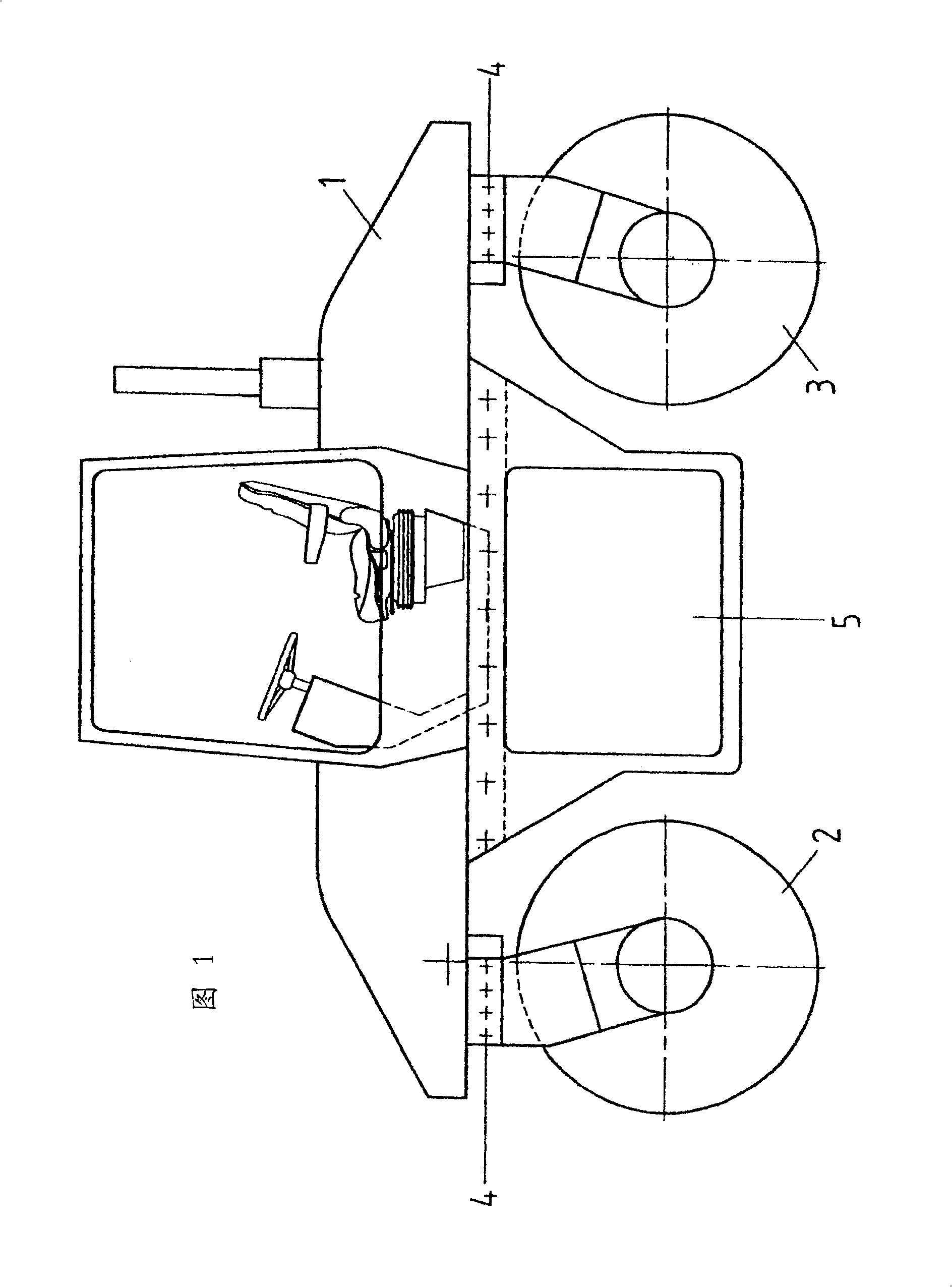
[0023] figure 1 The shown tandem roller comprises a superstructure 1 with a driver's cab, rolling bodies 2 and 3 mounted at the front and rear under said superstructure 1 via steerable swivel couplings 4 . Between the two rolling bodies 2, 3 is an engine compartment 5 in which the drive motor, usually a diesel engine, is housed.

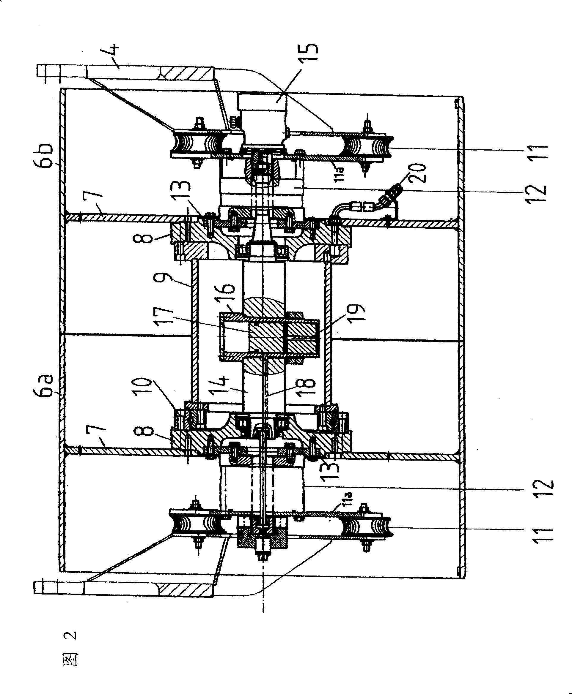
[0024] Such as figure 2 As shown, the front and / or rear rolling elements 2, 3 comprise two tire halves 6a, 6b arranged axially side by side and a corresponding radially extending tire end plate 7, the tire end plate 7 Has a central through hole. A corresponding bearing flange 8 is fastened on the tire end plate 7 . The two tire halves 6a, 6b are connected to each other so as to be rotatable about the axis of the rolling bodies via the two bearing flanges 8 and the spacer tube 9 via a bearing 10, for example arranged between the bearing flange 8 and the spacer tube 9 between the roller bearings.

[0025] The swivel coupling 4, which is steerably...


PUM


Abstract

The invention relates to a compacting roll comprising at least one rolling body (2, 3) with a vibratory drive comprising a drivable exciter shaft (14) with an unbalancer, said shaft facing the rolling body (2, 3) Axially installed in the rolling body, the unbalancer includes an unbalanced cylinder (16) arranged centrally relative to the rolling body, the unbalanced cylinder is supported by the actuator shaft (14), and has a The axis of the unbalanced piston (17) is hydraulically adjusted radially by means of an adjustment device.

Description

technical field [0001] The invention relates to a compacting roll having at least one rolling body with a vibratory drive comprising a drivable exciter shaft with an unbalancer, said shaft being axial to the rolling body Mounted in said rolling body, the unbalancer comprises an unbalance cylinder centrally arranged with respect to the axis of the rolling elements, and supported by the actuator shaft, and having an unbalance piston which can hydraulically rotate relative to the axis of the rolling elements and hydraulic fluid can be supplied to the unbalanced cylinder through a bore in the exciter shaft by means of an external adjustment device having a power cylinder with a power piston while continuously varying the nominal amplitude to suit the paving environment and the chamber communicating with the unbalance cylinder. Background technique [0002] In earthworks or road construction, it is desirable to compact unbound, hydraulically bound or bituminously bound material ...

Claims


Application Information

Patent Timeline
Patent Type & Authority Patents(China)
IPC IPC(8): E01C19/28E02D3/046B06B1/18F16C13/00
CPCE01C19/286
Inventor 理查德·斯特尔布林克斯蒂芬·瓦克斯曼
Owner ABG ALLG BAUMASCHINEN GMBH
Learn More