Load bridging method and device

A load offloading and load detection technology, which is applied in the direction of device selection, network traffic/resource management, and data exchange through path configuration, which can solve problems such as excessive cell load and shortage of spectrum resources.

Inactive Publication Date: 2009-08-19
HUAWEI TECH CO LTD
View PDF4 Cites 0 Cited by
  • Summary
  • Abstract
  • Description
  • Claims
  • Application Information

AI Technical Summary

Problems solved by technology

[0004] In view of this, the main purpose of the present invention is to provide a method and device for load distribution to solve the problem of shortage of spectrum resources caused by excessive cell load in a wireless communication system

Method used


Image

  • Load bridging method and device
  • Load bridging method and device
  • Load bridging method and device

Examples


Embodiment Construction

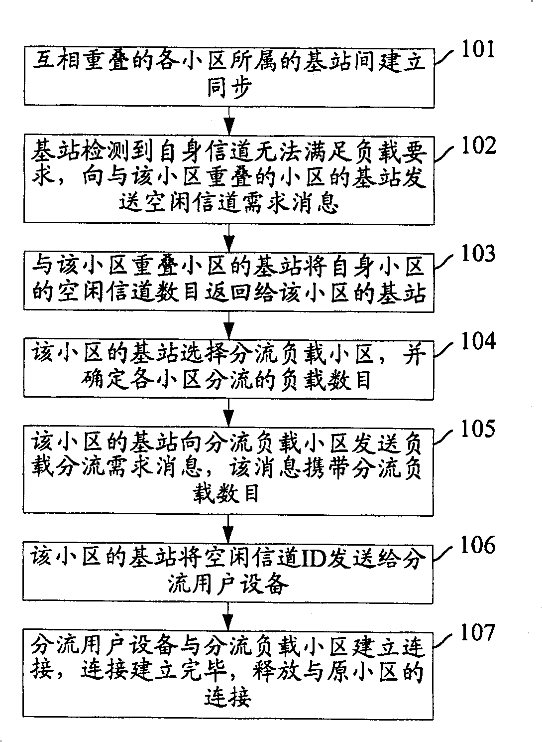
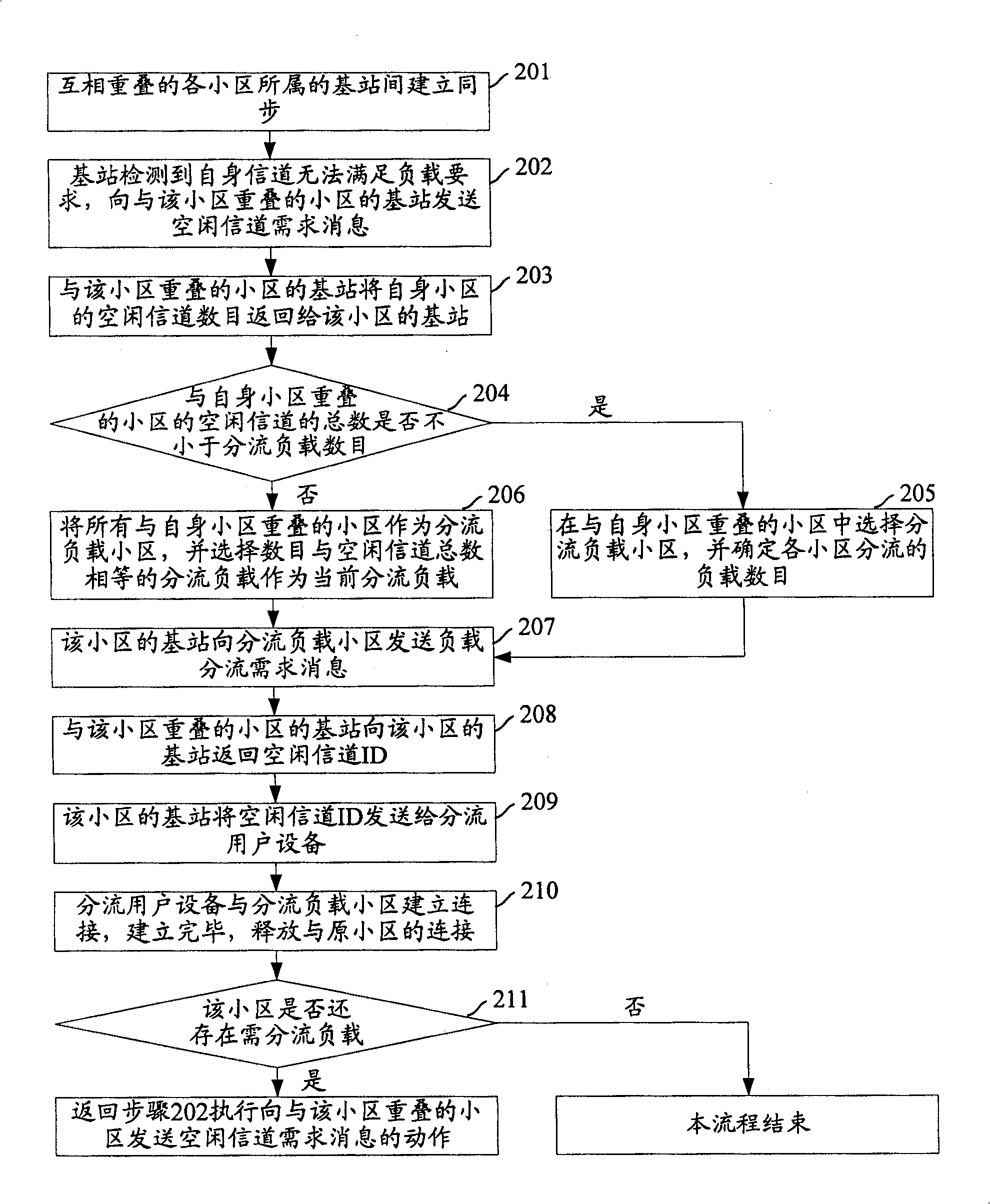
[0027] Because when the overlapping area between the cells is covered by different frequencies, the base station does not have interference in the overlapping area. Therefore, the core idea of ​​the present invention is to establish synchronization between the base stations of the overlapping cells. When the channel of a certain cell cannot meet the load requirement, the base station of the cell requests an idle channel from the base station of the cell overlapping with the cell. , and according to the number of free channels of the cell overlapping with the cell, select a cell that offloads its own load, and then offload the load of the cell to each offloading cell overlapping with the cell.

[0028] The present invention will be further described in detail below in conjunction with the accompanying drawings and specific embodiments.

[0029] figure 1 is the flow chart of the load distribution provided by the present invention, such as figure 1 As shown, the specific steps ...


PUM


Abstract

This invention discloses a method for load splitting including: setting up synchronization among overlapped base stations belonged to local areas, when a base station tests that the current channel of its own can' t meet the needs of load, it asks for idle channels to local areas superpositioned with it and sends the idle channel identifications returned by local areas to the splitted user devices. This invention also discloses a device including: a synchronization set up module, a load test module, a determining module for splitted load areas and a load splitting module.

Description

technical field [0001] The present invention relates to the technical field of wireless communication, in particular to a load sharing method and device. Background technique [0002] The wireless area network (WRAN) was proposed by the IEEE802.22 working group formally established by the International Institute of Electrical and Electronics Engineers (IEEE) in October 2004. The goal of this working group is to use a technology called cognitive radio, which will be assigned to The very high frequency (VHF) / ultra high frequency (UHF) frequency band of television broadcasting, for example: in North America, the frequency of this frequency band is 54MHz to 862MHz, which is used as a broadband access line. This is another new wireless frequency application technology after the "Ultra Wideband System (UWB)" that was realized for civilian use in 2002. The IEEE802.22 working group will formulate the specifications of the physical layer and the media access control (MAC) layer of w...

Claims


Application Information

Patent Timeline
Patent Type & Authority Patents(China)
IPC IPC(8): H04Q7/36H04B7/26H04L12/28H04L12/56H04W16/06H04W28/08H04W72/12
Inventor 吴舟吕林军
Owner HUAWEI TECH CO LTD
Why Eureka
Try Eureka