Active organic electroluminescent display panel and production thereof

A technology of electroluminescence display and manufacturing method, which is applied in the direction of electroluminescence light source, light source, electric light source, etc., to achieve the effect of improving brightness difference, uniform brightness, and improving display effect

Inactive Publication Date: 2009-08-26
CHUNGHWA PICTURE TUBES LTD
View PDF6 Cites 0 Cited by
  • Summary
  • Abstract
  • Description
  • Claims
  • Application Information

AI Technical Summary

Problems solved by technology

[0008] The purpose of the present invention is to overcome the defects of the existing active organic electroluminescent display panel and its manufacturing method, and provide a new active organic electroluminescent display panel and its manufacturing method. The technical problem is to provide an active organic electroluminescent display panel to improve the luminance difference caused by the different luminous efficiencies of various organic materials, thereby improving the display effect of the panel

Method used


Image

  • Active organic electroluminescent display panel and production thereof
  • Active organic electroluminescent display panel and production thereof
  • Active organic electroluminescent display panel and production thereof

Examples


no. 1 example

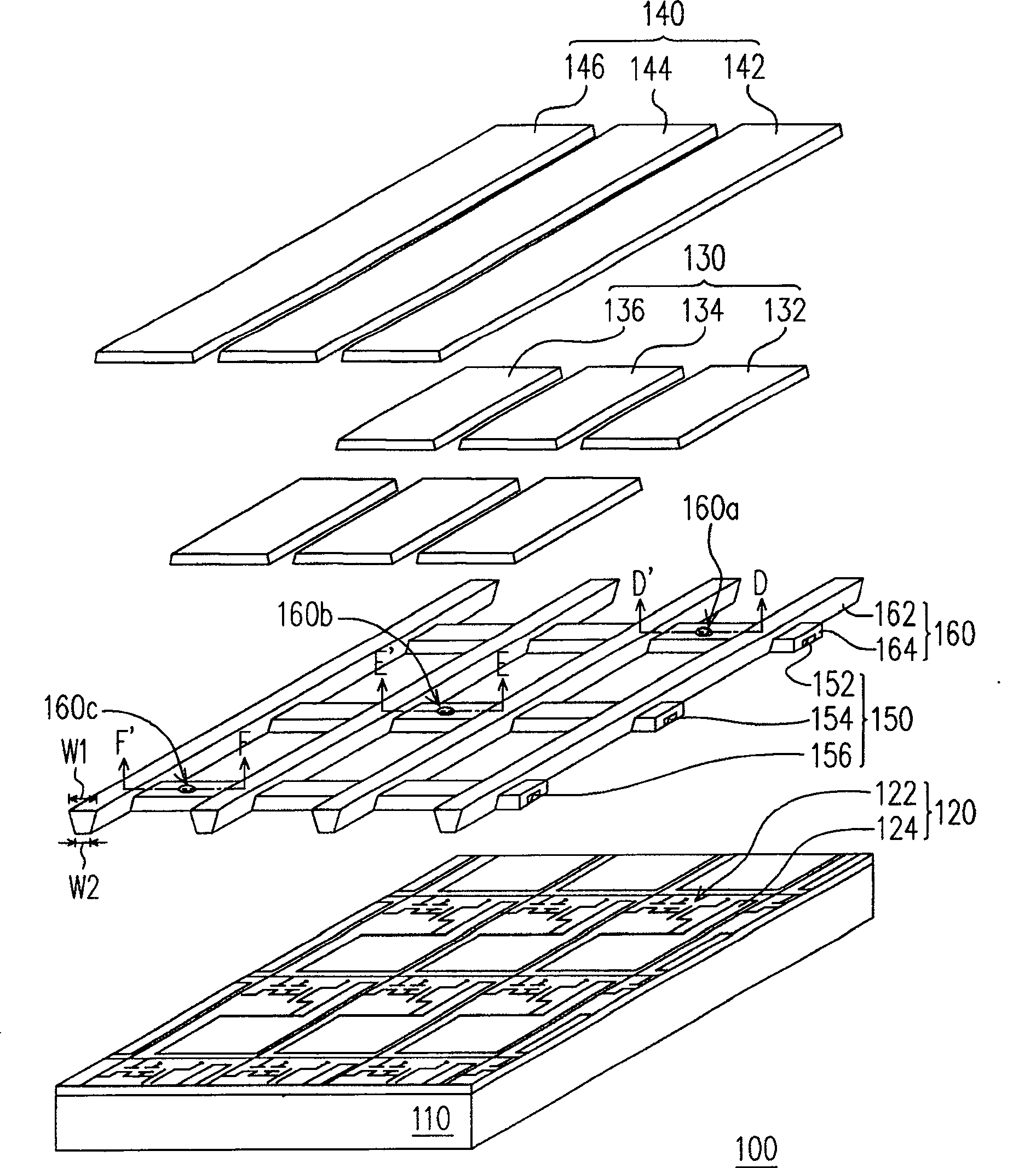
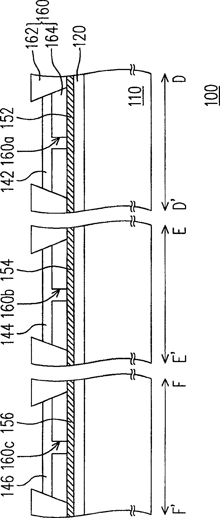
[0059] see Figure 1A and Figure 1B as shown, Figure 1A It is a structural schematic diagram of an active organic electroluminescence display panel according to a first preferred embodiment of the present invention. Figure 1Bis a schematic diagram of a partial cross-sectional structure of an active organic electroluminescence display panel according to a first preferred embodiment of the present invention, wherein Figure 1B The cross-sectional structure shown is along the Figure 1A D-D', E-E' and F-F' section lines. Please also see Figure 1A and Figure 1B The active organic electroluminescence display panel 100 includes a substrate 110 , a pixel structure layer 120 , an organic light emitting layer 130 and a cathode pattern layer 140 , wherein the pixel structure layer 120 is disposed on the substrate 110 . In addition, the pixel structure layer 120 includes, for example, an active element array 122 and an anode pattern layer 124, wherein the active element array 122 ...

no. 2 example

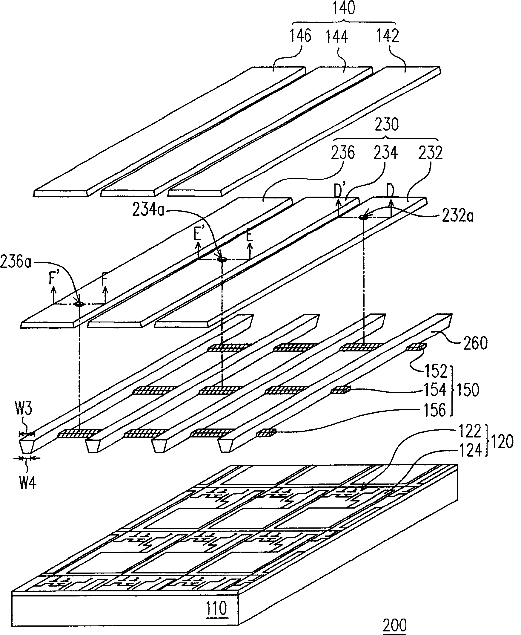
[0068] see Figure 2A and Figure 2B as shown, Figure 2A It is a schematic structural diagram of an active organic electroluminescence display panel according to a second preferred embodiment of the present invention. Figure 2B is a schematic diagram of a partial cross-sectional structure of an active organic electroluminescence display panel according to a second preferred embodiment of the present invention, wherein Figure 2B The cross-sectional structure shown is along the Figure 2A D-D', E-E' and F-F' section lines. If the number of the second embodiment is the same as that of the first embodiment, it means that the components specified in the second embodiment are the same as those specified in the first embodiment, and will not be repeated here.

[0069] see Figure 2A and Figure 2B As shown, the second embodiment is similar to the first embodiment, the difference is that the shapes of the first organic light emitting pattern 132, the second organic light emit...


PUM


Abstract

The present invention relates to an active organic electroluminescent display panel and its manufacturing method, wherein the active organic electroluminescent display panel includes a substrate, a pixel structure layer, an organic light emitting layer and a cathode pattern layer, wherein the pixel structure layer is configured on the substrate, and the pixel structure layer includes an active element array and an anode pattern layer. The organic light-emitting layer covers at least the anode pattern layer, wherein the organic light-emitting layer includes at least one first organic light-emitting pattern, at least one second organic light-emitting pattern and at least one third organic light-emitting pattern. The cathode pattern layer is arranged on the organic light-emitting layer, wherein the cathode pattern layer includes a first cathode pattern correspondingly arranged on the first organic light-emitting pattern, a second cathode pattern correspondingly arranged on the second organic light-emitting pattern, and a corresponding arrangement A third cathode pattern on the third organic light emitting pattern, and the first, second and third cathode patterns are not connected together.

Description

technical field [0001] The present invention relates to a display panel and a manufacturing method thereof, in particular to an active matrix organic electro-luminescent display panel (Active Matrix Organic Electro-Luminescent Display panel, AMOELD panel) and a manufacturing method thereof. Background technique [0002] The information and communication industry has become the mainstream industry today, especially portable communication and display products are the focus of development. Since the flat panel display is a communication interface between people and information, its development is particularly important. Among them, the organic electroluminescent display (Organic Electro-Luminescent Display, OELD) has the advantages of self-illumination, wide viewing angle, power saving, simple manufacturing process, low cost, wide operating temperature, high response speed and full color, etc., making it Has great potential, so it is expected to become the mainstream of the ne...

Claims


Application Information

Patent Timeline
Patent Type & Authority Patents(China)
IPC IPC(8): H05B33/26H05B33/12H05B3/08H05B3/10
Inventor 朱文国安宝桢
Owner CHUNGHWA PICTURE TUBES LTD
Why Eureka
Try Eureka