Elevation type triaxial connecting system for jet printing

A three-axis linkage, lifting mechanism technology, applied in printing, manipulators, typewriters, etc., can solve the problems of small starting torque inertia, narrow speed regulation range, low sensitivity, etc., and achieve good stability, simple control structure, and clear characters. Effect

Active Publication Date: 2009-09-02
BAOSHAN IRON & STEEL CO LTD
View PDF6 Cites 0 Cited by
  • Summary
  • Abstract
  • Description
  • Claims
  • Application Information

AI Technical Summary

Problems solved by technology

[0008] The purpose of the present invention is to provide a lifting type three-axis linkage mechanism for printing that is much simpler than that of six-axis linkage control, mainly to solve the problems of six-axis linkage control such as complex mechanism, low sensitivity, small starting torque inertia, and adjustment The technical problem of the narrow speed range, the technical solution of the present invention is: a lifting type three-axis linkage mechanism for inkjet printing, including a plane mechanism distributed by three-axis linkage and a lifting mechanism to realize the lifting of the plane mechanism, and the three-axis linkage plane mechanism is installed On the lifting mechanism, the planar mechanism has three degrees of freedom to rotate around the respective Z-axis, the lifting mechanism can move up and down along the Z-axis, the planar mechanism constitutes a mechanical arm, and the end of the mechanical arm is connected with the printing device to realize printing

Method used


Image

  • Elevation type triaxial connecting system for jet printing
  • Elevation type triaxial connecting system for jet printing

Examples


Embodiment Construction

[0025] based on the following figure 1 with figure 2 , illustrating a preferred embodiment of the present invention.

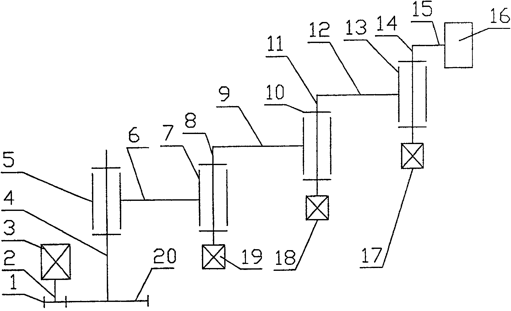
[0026] Such as figure 1 As shown, the lift-type three-axis linkage mechanism for jet printing provided by the present invention includes a plane mechanism and a lift mechanism;

[0027] The planar mechanism is provided with a mechanical arm device including three rotational degrees of freedom around the respective Z axes and a wrist device connected to the printing device;

[0028] Described lifting mechanism is provided with and comprises servomotor a 19, screw mandrel 4 (ball screw can be used), bull gear 20, pinion 1 and lifting frame 5, and screw mandrel 4 is installed on lifting frame 5, and bull gear 20 and the screw are connected as one, the large gear and the pinion 1 mesh, the pinion 1 is connected with the output shaft 2 of the servo motor, the AC servo motor 19 drives the pinion 1 to realize the main rotation, and the large gear 20 and the screw...


PUM


Abstract

The invention relates to a transmission mechanism of a jet printing machine, in particular to a lifting type three-axis linkage mechanism for jet printing. It mainly solves the technical problems of complex mechanism, low sensitivity, small starting torque inertia and narrow speed regulation range existing in the six-axis linkage control. The technical solution of the present invention is: an elevating three-axis linkage mechanism for spray printing, including a plane mechanism distributed by three-axis linkage and a lifting mechanism for realizing the lifting of the plane mechanism. The three-axis linkage plane mechanism is installed on the lifting mechanism, and the plane mechanism has three Two degrees of freedom of rotation around the respective Z-axis, the lifting mechanism can move up and down along the Z-axis, the plane mechanism constitutes the mechanical arm, and the end of the mechanical arm is connected with the printing device to realize printing. The mechanical arm contains three degrees of freedom of rotation around their respective Z axes. The three degrees of freedom of rotation around their respective Z axes enable the mechanical arm to perform relative linkage through three rotations around their respective Z axes in a fixed plane, realizing steel The arc trajectory required for roll printing; the above four degrees of freedom, according to the instructions from the microcomputer, coordinate with each other and run according to the required trajectory and speed. The invention is mainly used in jet printers.

Description

Technical field: [0001] The invention relates to a transmission mechanism of a jet printing machine, in particular to a lifting type three-axis linkage mechanism for jet printing. Background technique: [0002] The spray printing equipment is a fully automatic marking system controlled by a computer, which directly forms marks on the side surface and top surface of the steel coil by spraying dot matrix. At present, the hot-rolling production lines of domestic and foreign iron and steel enterprises generally use dot-matrix inkjet printing for hot-steel coil labeling. Dot-shaped paint is sprayed on the position to form characters with dots. Because the jet printer also includes a sensor and has a relatively large mass, the side spray on the side surface of the steel coil and the top spray on the top surface of the steel coil are mostly separately controlled by the jet printer. [0003] At present, a articulated robot with 6-axis linkage is used, which performs top spraying a...

Claims


Application Information

Patent Timeline
Patent Type & Authority Patents(China)
IPC IPC(8): B25J1/00B25J18/00B41J3/407
Inventor 王军
Owner BAOSHAN IRON & STEEL CO LTD
Why Eureka
Try Eureka