
Three-way electromagnetical valve

An electromagnetic three-way valve and electromagnetic control technology, applied in the direction of rotary piston machinery, machine/engine, rotary piston pump, etc., can solve the problems of low life, high cost, complex structure, etc., and achieve long life, low cost, The effect of simple structure

Active Publication Date: 2009-09-02
ZHEJIANG DUNAN ARTIFICIAL ENVIRONMENT
View PDF5 Cites 1 Cited by
  • Summary
  • Abstract
  • Description
  • Claims
  • Application Information

AI Technical Summary

Problems solved by technology

[0004] Although the four-way reversing valve or the three-way reversing valve rebuilt from the four-way reversing valve can meet the control requirements for controlling the rotary compressor, but because the four-way reversing valve and the three-way reversing valve rebuilt from the four-way reversing valve The directional valve belongs to the sliding structure of the spool driven by electromagnetic suction, which has complex structure, high cost and low service life

Method used


Image

  • Three-way electromagnetical valve
  • Three-way electromagnetical valve
  • Three-way electromagnetical valve

Examples


Embodiment Construction

[0044] The preferred embodiments of the novel electromagnetic three-way valve of the present invention will be described in detail below with reference to the accompanying drawings.

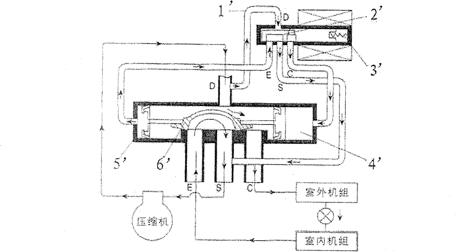
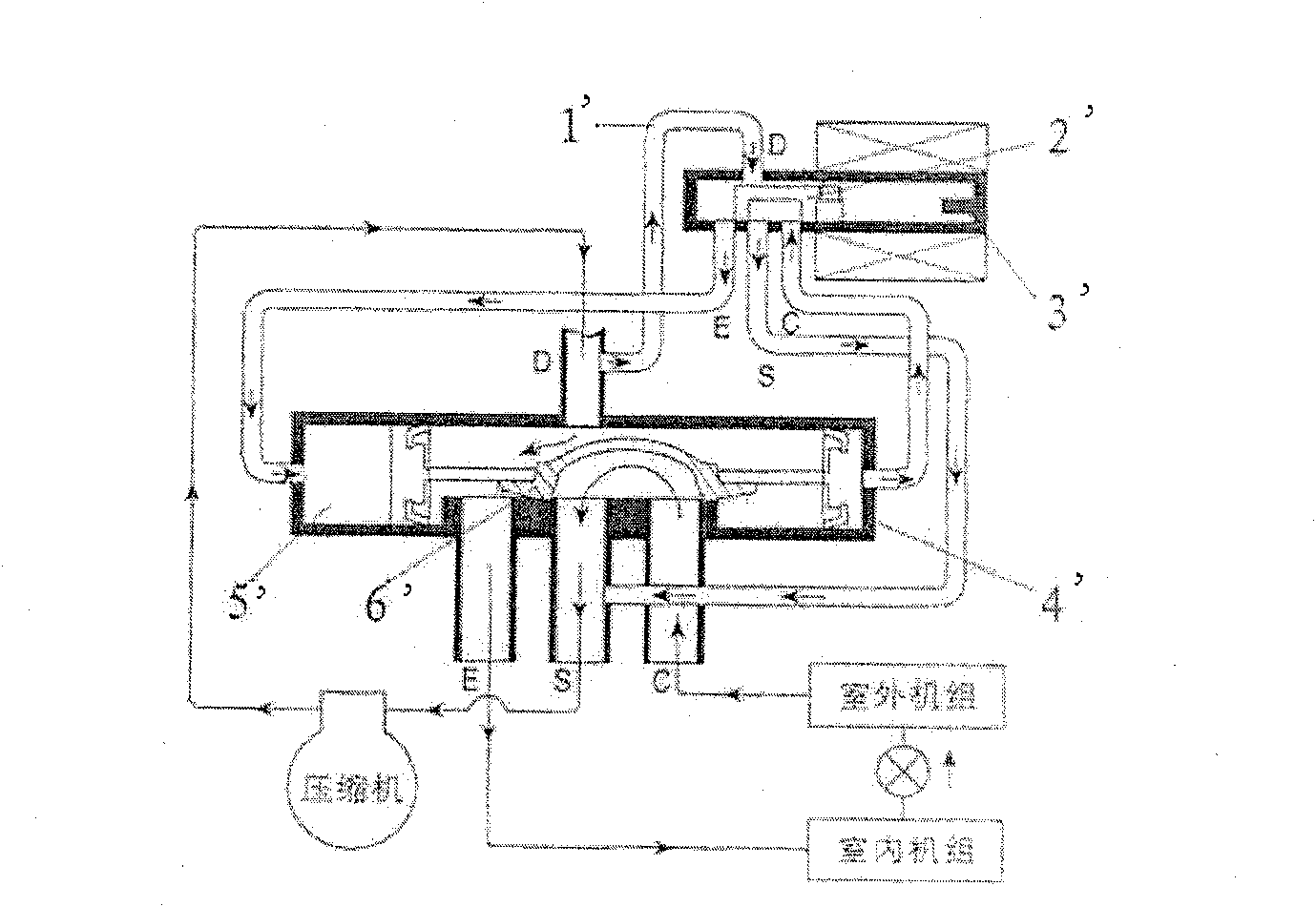
[0045] Figure 4 It is a cross-sectional view of a preferred embodiment of the present invention, which shows the internal structure of the electromagnetic three-way valve of the present invention. As shown in the figure, the new electromagnetic three-way valve includes an electromagnetic control component part, a valve body 6, and a high-pressure cut-off valve part.

[0046] see Figure 4 , which shows a typical structure of the electromagnetic control assembly part, which includes an outer tube 13, an electromagnetic coil 3 located outside the outer tube 13, and a static iron core (fixed iron core) 1 and a soft magnet (moving iron core) located in the outer tube 13 Core) 4, wherein a first elastic element such as a compression spring 2 is arranged between the static iron core 1 and the moving ...


PUM


Abstract

The invention relates to an electromagnetic three-way valve for controlling a compressor, comprising: a valve body (6), one end of which is connected to an electromagnetic control assembly, and the inside of the valve body includes a first chamber (A) and a second chamber ( B), the first chamber (A) communicates with the first connecting pipe (11), and the second chamber (B) communicates with the second connecting pipe (12); the electromagnetic control assembly is used to control the first The on-off between the chamber (A) and the second chamber (B); and the high-pressure cut-off valve assembly, used to control the on-off between the second connecting pipe (12) and the third connecting pipe (7), wherein , when the second chamber communicates with the first chamber, the high-pressure cut-off valve assembly is affected by the high-pressure gas entering the second chamber to block the communication between the second chamber and the third chamber ; and after the second chamber is cut off from the first chamber for a predetermined period of time, the communication between the second chamber and the third chamber is resumed. The present invention also relates to a method for controlling the operation mode of the compressor using the above-mentioned electromagnetic three-way valve.

Description

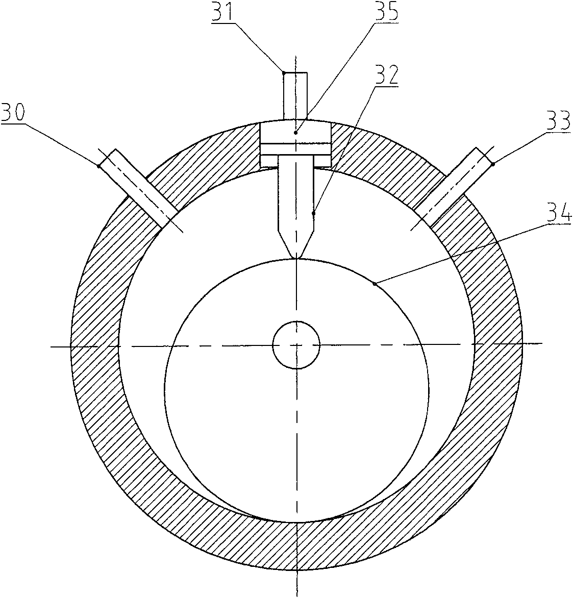
technical field [0001] The invention relates to an adjustment and control device for a refrigeration system, in particular to an electromagnetic three-way valve for controlling a rotary compressor. Background technique [0002] In the existing refrigeration system, a four-way reversing valve or a three-way reversing valve modified from an electromagnetic four-way reversing valve is usually used to control the rotary compressor (also called capacity compressor, variable capacity compressor) , the structure of the existing rotary compressor is as follows figure 1 As shown, when the cylinder 35 presses the valve plate 32 against the rotor 34, the rotation of the rotor 34 compresses the gas, and the gas is sucked and exhausted through the inlet pipe 30 and the outlet pipe 33, whether the compressor is compressed or not Controlled by the movement of the cylinder 35, the movement of the cylinder controls whether the valve plate 32 compresses or not compresses the rotor 34, and th...

Claims


Application Information

Patent Timeline
Patent Type & Authority Patents(China)
IPC IPC(8): F04C28/00F04C18/356
Inventor 何国平黄长金
Owner ZHEJIANG DUNAN ARTIFICIAL ENVIRONMENT
Learn More