
Electronic switch for voltage stabilization and power consumption minimization

An electronic switch and current technology, applied in the direction of electric switch, time program switch, circuit, etc., can solve the problems of power consumption and stability of 2-wire electronic switch

Inactive Publication Date: 2009-09-09
JOONG ANG CONTROL CO LTD
View PDF2 Cites 0 Cited by
  • Summary
  • Abstract
  • Description
  • Claims
  • Application Information

AI Technical Summary

Problems solved by technology

[0009] The object of the present invention is to provide an electronic switch which utilizes two input wires but which overcomes the problems in the installation of conventional 3-wire electronic switches as well as the problems of power consumption and power stability of conventional 2-wire electronic switches

Method used


Image

  • Electronic switch for voltage stabilization and power consumption minimization
  • Electronic switch for voltage stabilization and power consumption minimization
  • Electronic switch for voltage stabilization and power consumption minimization

Examples


Embodiment Construction

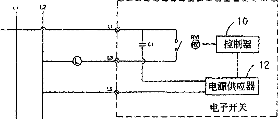
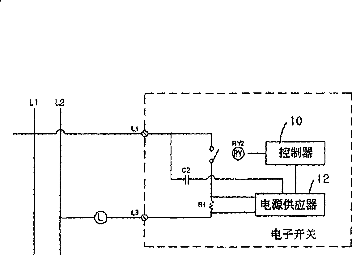
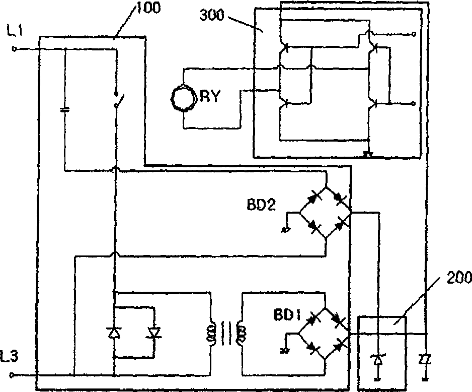
[0024] image 3 An overall schematic diagram of the electronic switch of the present invention is shown. As shown, the present invention utilizes only two lines L1 and L3. image 3 only means as figure 1 and 2 The configuration of the electronic switch indicated by the dashed line in . Since the connection to the external power line and the wiring related to the lamp are different from figure 1 and 2 are the same as those of , so descriptions of these items will be omitted.

[0025] see image 3 , the configuration of the present invention will be described. The present invention is an electronic switch having first and second wires connected across a light for electronically turning the light on and off. Electronic switches consist of the following parts:

[0026] a power supply 100 comprising a pair of diodes D1, D2, each of which is inserted in series between first and second lines L1, L3, and both of which are connected in parallel with opposite polarities; a tran...


PUM


Abstract

The present invention provides an electronic switch that utilizes two input wires but overcomes the problems in the installation of conventional 3-wire electronic switches and the problems of power consumption and power stability of conventional 2-wire electronic switches. The switch comprises a) a power supply comprising a pair of diodes each inserted in series between the first and second lines with the diodes connected in parallel with opposite polarities; a transformer for stepping up across the diodes and the emerging voltage; a first rectifier for rectifying the boosted AC to DC; a second rectifier for rectifying the current from the first wire when the first and second wires are disconnected due to the lamp being off, b) a voltage regulator comprising a zener diode for suppressing an abnormal rise in the output voltage of the power supply, and c) a relay driver comprising a relay operated by a DC voltage from the power supply, the relay being a self- Holding relays, once activated by current flowing through the coil, the relay remains activated even if the voltage is removed.

Description

technical field [0001] The invention relates to an electronic switch. More specifically, the present invention relates to an electronic switch for obtaining power for electrical appliances and for minimizing power consumption. Background technique [0002] Switches for turning lights and appliances on and off have recently evolved into remote controls for convenience and safety, or electronic switches operated by electronic circuits. [0003] Conventional 3-wire electronic switch [0004] A conventional light switch has two terminals where if the terminals are connected the light is on and vice versa. Electronic switches for lamp applications, on the other hand, consist of a combination of relays and SCRs or triacs. figure 1 A typical schematic diagram of an electronic switch is shown in . The controller 10 is used to control and drive the relay RY1. The controller 10 can be configured to automatically turn the lights on in the morning with the help of a built-in clock,...

Claims


Application Information

Patent Timeline
Patent Type & Authority Patents(China)
IPC IPC(8): H01H43/02
CPCH01H47/02
Inventor 申尚熙
Owner JOONG ANG CONTROL CO LTD
Features
  • Generate Ideas
  • Intellectual Property
  • Life Sciences
  • Materials
  • Tech Scout
  • Unparalleled Data Quality
  • Higher Quality Content
  • 60% Fewer Hallucinations
Learn More