Method for installing temperature probe of conduction cooling superconducting magnet
A technology of superconducting magnets and temperature probes, applied to thermometers, parts of thermometers, measuring devices, etc., to achieve the effect of ensuring tightness and easy installation
Inactive Publication Date: 2011-01-05
INST OF ELECTRICAL ENG CHINESE ACAD OF SCI
View PDF0 Cites 0 Cited by
- Summary
- Abstract
- Description
- Claims
- Application Information
AI Technical Summary
Problems solved by technology
The purpose of the present invention is to overcome the problem of temperature probe installation in key parts of the conduction cooling superconducting magnet system, and propose a new temperature probe installation method
Method used
View moreImage
Smart ImageViewing Examples

Examples
Embodiment Construction
Login to View More PUM
| Property | Measurement | Unit |
|---|---|---|
| Thickness | aaaaa | aaaaa |
Abstract
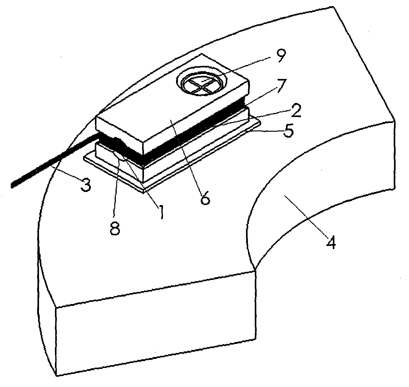
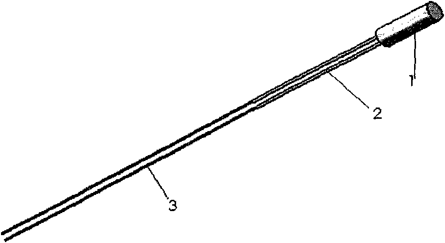
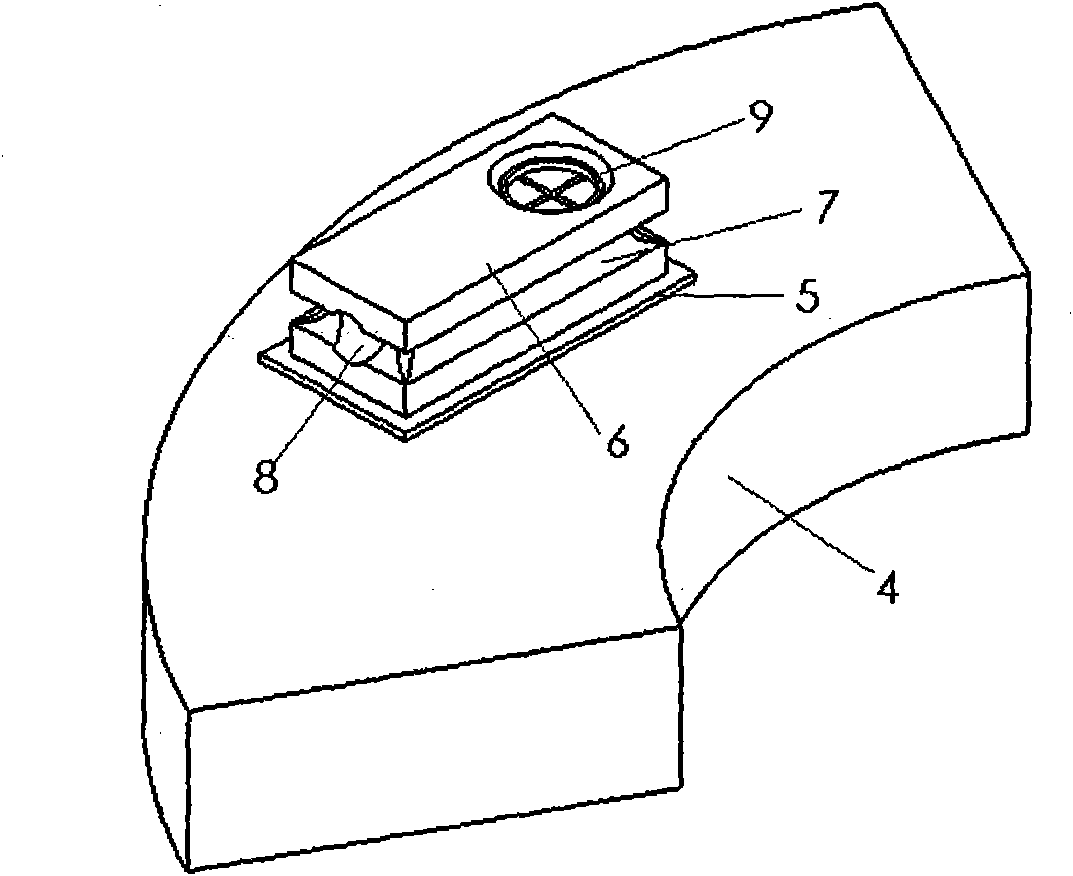
The invention relates to a method for installing a temperature probe of a conduction cooling superconducting magnet, which is characterized in that firstly, a length of thin copper wire (2) with an insulation layer is welded on a lead-out wire of a temperature probe (1), and then a length of thin manganin wire (3) with an insulation layer is welded and is connected with the thin copper wire; the thin manganin wire (3) is connected to the outside of a superconducting magnet; the temperature probe (1) is arranged in a round hole (8) of the front of a heat sink (6) of a cuboid made of a high-purity copper material; gaps between the temperature probe (1) and the wall of the round hole (8) are filled with high-thermal conductivity silicone grease; the heat sink (6) is arranged at a detected position of the superconducting magnet; an indium foil sheet is adhered between the bottom surface of the heat sink (6) and the surface of the detected position of the superconducting magnet, and a boltis utilized to tightly press the heat sink (6) on the surface of the detected position (4) of the superconducting magnet; the thin copper wire (2) is wrapped in semicircle grooves (7) around the heatsink (6), and gaps between the thin copper wires (2) are filled with the silicone grease.
Description
A method for installing a conduction cooling superconducting magnet temperature probe technical field The invention relates to an installation method of a temperature probe used for temperature measurement of key parts of a conduction cooling superconducting magnet. Background technique In the late 1990s, the technology of conduction-cooled superconducting magnets developed rapidly, gradually replacing liquid helium-immersed superconducting magnets. Compared with the traditional liquid helium soaked superconducting magnet system, the conduction cooling superconducting magnet does not use liquid helium to cool, but uses a two-stage G-M refrigerator as a cold source to cool the superconducting magnet. Since the entire superconducting magnet is cooled by a single cold source by heat conduction, the connection between the various parts of the superconducting magnet must be tight, and the heat conduction must be very good, and the secondary cold head of the refrigerator has onl...
Claims
Login to View More Application Information
Patent Timeline
 IPC IPC(8): G01K1/14
Inventor 陈顺中王秋良雷沅忠
Owner INST OF ELECTRICAL ENG CHINESE ACAD OF SCI

PatSnap Eureka turns technology decisions into work you can execute. Powered by our Innovation Knowledge Graph, it runs expert workflows across engineering, life sciences, materials and intellectual property. Get your review-ready output in minutes.


