

Dishware cleaning machine
A dishwashing machine and dishware technology, which is applied to dishwashing machine/washing machine, dishwashing machine/rinsing machine parts, automatic detection under the control of dishwashing machine/rinsing machine, etc., can solve the problem that the washing tank cannot be guaranteed Sealing and other problems, to achieve the effect of simple device structure and prevention of liquid leakage
- Summary
- Abstract
- Description
- Claims
- Application Information
AI Technical Summary
Problems solved by technology
Method used
Image

Examples
no. 1 Embodiment
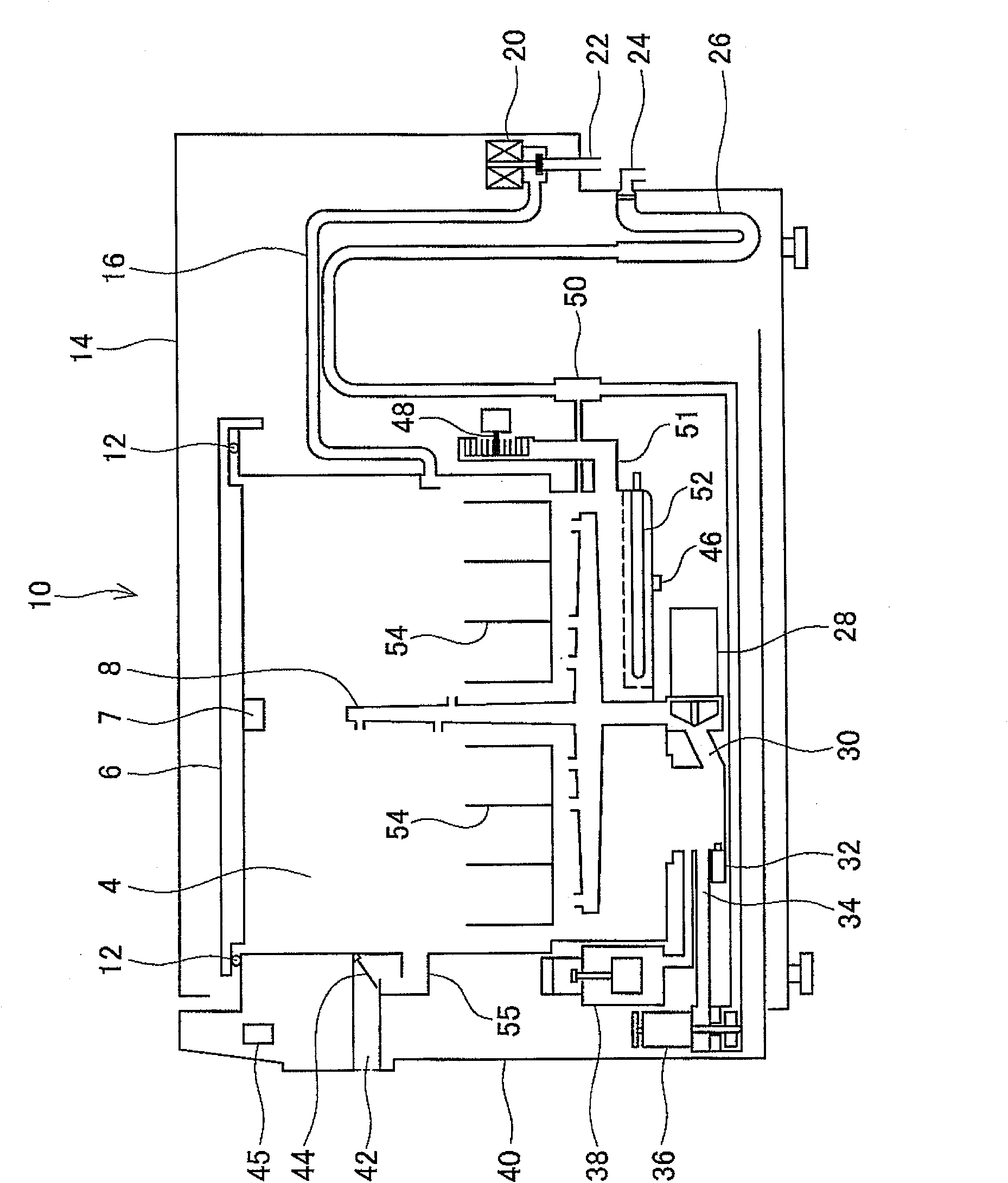
[0037] figure 1 It is a sectional view schematically showing the dishwasher 10 of the first embodiment. Inside the housing 14 of the dishwasher 10 is provided a washing tank 4 for washing and drying various kinds of dishes stored in the dish basket 54 . The cleaning tank 4 has a box shape having an opening at the top, and a door 40 is provided on the front surface. The cleaning tank 4 can be pulled out from the casing 14, and then various tableware can be taken out from the upper opening of the cleaning tank 4.
[0038]Inside the casing 14 is provided an upper cover 6 that seals the upper opening of the cleaning tank 4 . The range of movement of the upper cover 6 is limited by a guide member not shown in the figure. After the cleaning tank 4 is pulled out from the casing 14, the upper cover 6 is obliquely upward relative to the cleaning tank 4 ( figure 1 upper left in ) and then stops inside the housing 14. After the cleaning tank 4 is pushed into the shell 14, the upper c...
no. 2 Embodiment
[0065] Description of the same parts as those in the first embodiment will be omitted. The dishwasher 10 of this embodiment has the same structure as that of the first embodiment, but the content of the operation is different.
[0066] The following combination Figure 5 The operation content of the dishwasher 10 of this embodiment will be described.
[0067] After the dishwasher 10 starts to operate in step S32, the washing tank 4 drives the drain pump 36 in step S34 to discharge the water stored in the bottom of the washing tank 4 from the washing tank 4.
[0068] In step S36, it is judged whether the minimum water level switch 32 is closed, and if the minimum water level switch 32 is connected (no situation in step S36), the controller 45 makes the judgment of unfinished drainage, and enters step S38 . In step S38, it is determined whether or not the elapsed drainage time from the start of drainage has reached 3 minutes. If the drainage has not been completed and 3 minu...
no. 3 Embodiment
[0081] Below, combine Figure 6 to Figure 8 Another dishwasher 100 of the present invention will be described.
[0082] The same reference numerals are assigned to the same parts as those of the dishwasher 10 in the first and second embodiments, and description thereof will be omitted.
[0083] Figure 6 It is a sectional view schematically showing the dishwasher 100 of this embodiment. The structure of the dishwasher 100 is basically the same as that of the dishwasher 10. The dishwasher 100 does not have the pressure sensor 7, but has a displacement gauge 9 (equivalent to a detection mechanism for detecting pressure fluctuations) instead. The displacement gauge 9 is a contact displacement gauge. , which is arranged outside the center of the upper cover 6 . Displacement meter 9 has measured loam cake 6 in the direction perpendicular to upper surface ( Figure 6 The displacement in the up and down direction) and output the measured result to the controller 45.
[0084] F...
PUM
 Abstract
Description
Claims
Application Information