High efficiency cooling facility of cooling mechanism

A cooling mechanism and cooling device technology, applied in refrigerators, refrigeration components, refrigeration and liquefaction, etc., can solve the problems of scaling and rusting of power devices, affecting the service life of power devices, etc.

Inactive Publication Date: 2009-10-07
LASER TEK TAIWAN
View PDF6 Cites 0 Cited by
  • Summary
  • Abstract
  • Description
  • Claims
  • Application Information

AI Technical Summary

Problems solved by technology

[0003] In the above-mentioned existing cooling device, when the power unit drives the sprinkler pan to rotate, the cooling water on the sprinkler pan and the moisture in the air will enter the interior of the power unit as the power unit operates, causing the power Scale and rust are generated inside the device, which seriously affects the service life of the power device

Method used


Image

  • High efficiency cooling facility of cooling mechanism
  • High efficiency cooling facility of cooling mechanism
  • High efficiency cooling facility of cooling mechanism

Examples


Embodiment Construction

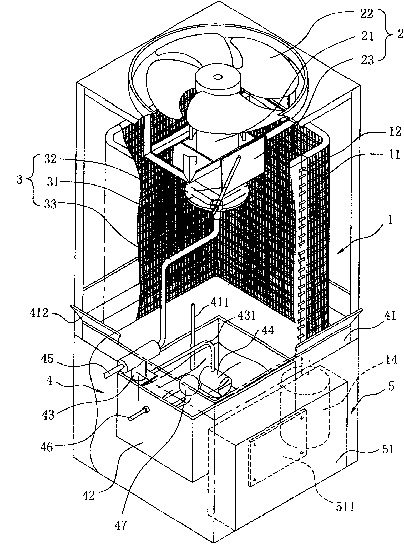
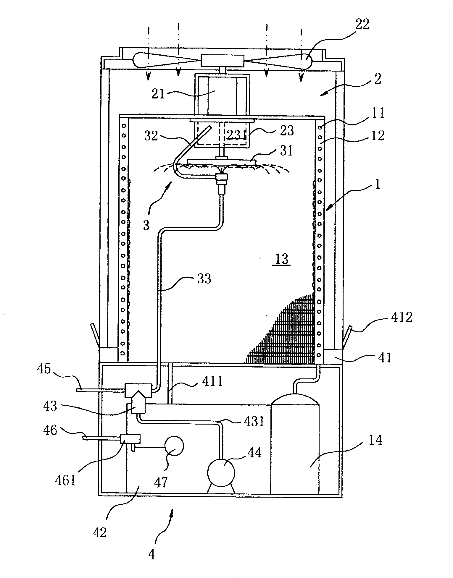
[0046] see figure 1 and figure 2 As shown, the present invention provides a high-efficiency cooling device for a cooling mechanism. The cooling mechanism can be a mechanism with a cooling function such as an air conditioner, a freezer, or a refrigerator. The cooling device includes: a heat exchange unit 1, an air cooling unit 2. A water cooling unit 3 , a water circulation unit 4 and a control unit 5 .

[0047] The heat exchanging unit 1 has a refrigerant pipe 11 and several heat dissipation fins 12 that are dense and juxtaposed. The refrigerant pipe 11 is continuously wound around the heat dissipation fins 12 and formed into an upright ring frame structure, forming a hollow space surrounded by a frame. The chamber 13, the refrigerant pipe 11 is connected to the compressor 14 and the evaporator (not shown), forming a refrigerant circulation system. The refrigerant pipe 11 is filled with a heat transfer medium refrigerant, which absorbs heat in the evaporator to form a gaseo...


PUM


Abstract

A high-efficiency cooling device for a cooling mechanism, which is mainly fixedly connected to the first water supply pipe by a bracket, so that the first water supply pipe can spray cooling water from bottom to top toward the sprinkler tray, and then utilizes the functions of the water cooling unit and the air cooling unit to make the The cooling water can be evenly sprinkled to the heat exchange unit, allowing the high-temperature gaseous refrigerant to release heat energy to cool down and condense into a liquid refrigerant. And the waterproof cover is arranged under the power unit, and the first water supply pipe sprays cooling water from bottom to top towards the sprinkler plate, so as to prevent the cooling water and moisture in the air during the circulation of the water-cooling unit from being brought in with the operation of the power unit. Inside the power unit, causing rust inside the power unit.

Description

technical field [0001] The invention relates to a high-efficiency cooling device for a cooling mechanism, especially a cooling device used in related cooling mechanisms such as an air conditioner, a freezer, or an outdoor unit of a refrigerator, and uses water cooling and air cooling for heat exchange . Background technique [0002] Existing cooling devices, such as China Taiwan Bulletin No.: 392835 (announcement date: June 01, 2000) promptly disclose a kind of " high-efficiency cooling device of cooling mechanism", which includes: a heat exchange unit, composed of careful A plurality of heat dissipation fins and a vertical ring frame structure composed of refrigerant pipes continuously passing through these heat dissipation fins form a hollow chamber surrounded by a frame; a water cooling unit is installed on the heat exchange unit The hollow chamber includes at least one sprinkler pan driven by the power device and a first water supply pipe for supplying cooling water to ...

Claims


Application Information

Patent Timeline
Patent Type & Authority Patents(China)
IPC IPC(8): F28D3/02F25B39/04
Inventor 田昌文
Owner LASER TEK TAIWAN
Why Eureka
Try Eureka