Apparatus direct mounting connector

A technology for installing equipment and connectors, which is applied in the direction of connection, parts of connecting devices, and structural parts of conversion equipment, etc. The effect of improving operability, improving connection operability and connection quality, and improving design freedom and versatility

Active Publication Date: 2009-10-14
YAZAKI CORP +1
View PDF8 Cites 7 Cited by
  • Summary
  • Abstract
  • Description
  • Claims
  • Application Information

AI Technical Summary

Problems solved by technology

[0013] However, in the above existing ( Figure 11 ~ Figure 12 ) connectors for direct mounting equipment and connection structures using them, such as Figure 14 As shown, there is a problem in that circuits 65 to 67 for connecting the main body (inverter) 64a of the device and bus bars (UVW) of each pole (UVW) of each connector 61, 61' in the case of the device 64 are not fixed. Cable distribution (rope distribution) is complicated, and equipment 64 is enlarged
In addition, since the circuits 65 to 67 are complicated, the connection operation is troublesome, requiring many man-hours, and connection errors may occur.
[0014] In addition, the circuits 65 to 67 in the equipment are used to manage the current value, and a current sensor for the management is installed in the equipment, so the size of the equipment 64 is increased.
[0015] In addition, the above existing ( Figure 15 ) of the bus bar structure 110 is connected to the connection conductor and the connection plate via the terminal plate, but for example, when the bus bar structure 110 is applied to a connector for direct mounting equipment (substantially does not exist), in order to Figure 16 One end portion 116 of the bus bar 113 is arranged in the housing of the device 121 shown, and the middle portion of the bus bar 113 is bent and arranged in the connector 122 for direct mounting equipment, and at the same time, the other end portion 119 of the bus bar 113 protrudes vertically and parallelly in the horizontal direction. , and in this state from the protruding direction (horizontal direction) of the other end portion 119 of the bus bar 113 to connect the opposite side connector (hand-side connector) 123, there may be a problem that the connector connection structure becomes enlarged toward the protruding direction of the bus bar
[0016] In addition, in Figure 17 As shown, in the case where the two bus bars 124 are bent upward in the connector 125 for direct mounting equipment and the counterpart connector 126 is connected downward, since the other ends 127 of the bus bars 124 are arranged in two front and rear Therefore, there may be a problem that the connection structure, that is, the arrangement direction (horizontal direction) of the connectors 125 for direct mounting equipment at the other end 127 of the bus bar becomes enlarged.

Method used


Image

  • Apparatus direct mounting connector
  • Apparatus direct mounting connector
  • Apparatus direct mounting connector

Examples


Embodiment Construction

[0056] The specific embodiment of the present invention will be described in detail below according to the accompanying drawings.

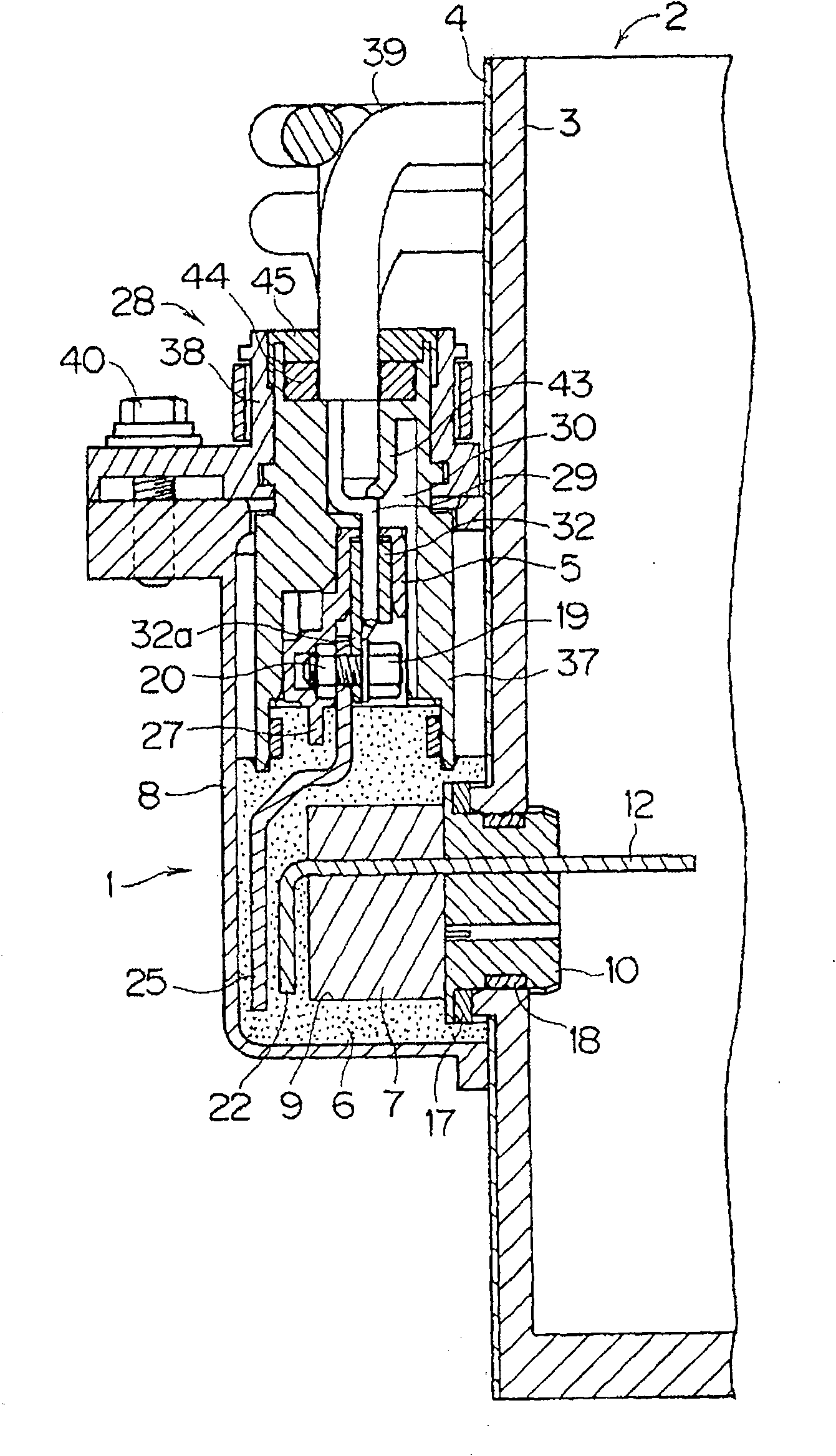
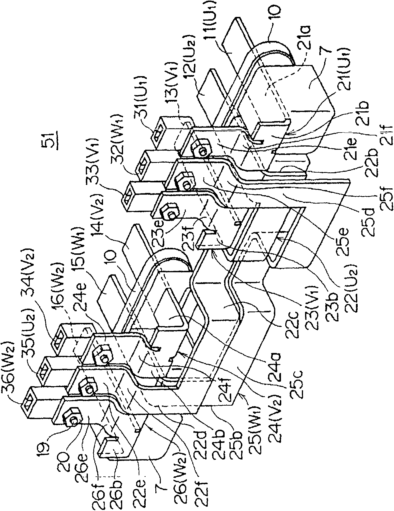
[0057] figure 1 Showing one embodiment of the connector for direct mounting equipment of the present invention, figure 2 An embodiment of a wiring structure of a bus bar to which a device connector is directly mounted is shown.

[0058] The direct mount device connector 1 has at least six terminal portions 11 to 16 ( figure 2 ) of six busbars 21-26; female terminals (terminal parts) 31-36 ( figure 2 ); housing 5 made of insulating resin for accommodating female terminals 31-36; insulating resin part (housing) 6 for insulating and fixing bus bars 21-26 by insert molding; current sensor 7 disposed in insulating resin part 6; covering insulation Resin part 6 and sealing cover 8 made of conductive metal of case 5 .

[0059] The terminal parts 11-16 of the six busbars 21-26 are arranged according to the pole sequence of UUVVWW, and each of the ...


PUM


Abstract

The present invention provides a direct-installation equipment connector for realizing miniaturization of an inverter (equipment) connecting two motors and a connection structure, which has six terminals for connecting two auxiliary machines and one equipment for three-phase AC Independent busbars (21~26), two U-pole terminals (11, 12), two V-pole terminals (13, 14), two W-pole terminals ( 15, 16) are respectively adjacently arranged, and each terminal part (11-16) is provided on one end side of each bus bar (21-26), and on the other end side of each bus bar, respectively in a separated state, as two groups of adjacent The terminal parts (31-33, 34-36) for each of a U pole, a V pole, and a W pole connected to the above-mentioned two auxiliary machines are arranged in a manner. The bus bars (22, 25) have extension portions (22c, 25c) extending between the two sets of terminal portions (31-33, 34-36) on the other end side. The bus bars (21-26) are molded on the insulating resin part.

Description

technical field [0001] The present invention relates to a connector for direct mounting equipment having a bus bar for connecting two three-phase AC motors (auxiliary machines) and an inverter (equipment) of an electric vehicle, for example. Background technique [0002] Figure 11 ~ Figure 12 This shows a conventional method of directly mounting a connector for equipment (for example, refer to Patent Document 1). [0003] The direct mounting equipment connector 61 is arranged on three-phase AC motors 62, 63 ( Figure 13 ) on the housing of the converter (equipment) 64 (represented by symbol 64), there are circuits 65-67 with the UVW three poles on the equipment side ( Figure 4 ) corresponding to the three bus terminals 68-70, the wires 73 with terminals connected to the bus terminals 68-70 by bolts 71, the housing 74 made of insulating resin for accommodating the terminals 72, and the shell 74 for covering the outside of the housing 74. The sealing cover 75 made of condu...

Claims


Application Information

Patent Timeline
Patent Type & Authority Patents(China)
IPC IPC(8): H01R13/405B60L11/18H02K5/22
CPCH01R29/00H01R31/065H01R25/162H01R13/42H02M7/003H01R13/40H01R13/405
Inventor 松本光弘福岛宏高塚本节芝健史郎渡边智冈本好司
Owner YAZAKI CORP
Why Eureka
Try Eureka