Heliostat device
A technology of heliostat and plane mirror, applied in the field of solar energy application, can solve the problems of aggravating the inherent system error of the heliostat device, unable to meet high-precision tracking, etc., and achieve the effect of eliminating the inherent system error
- Summary
- Abstract
- Description
- Claims
- Application Information
AI Technical Summary
Problems solved by technology
Method used
Image

Examples
Embodiment 1
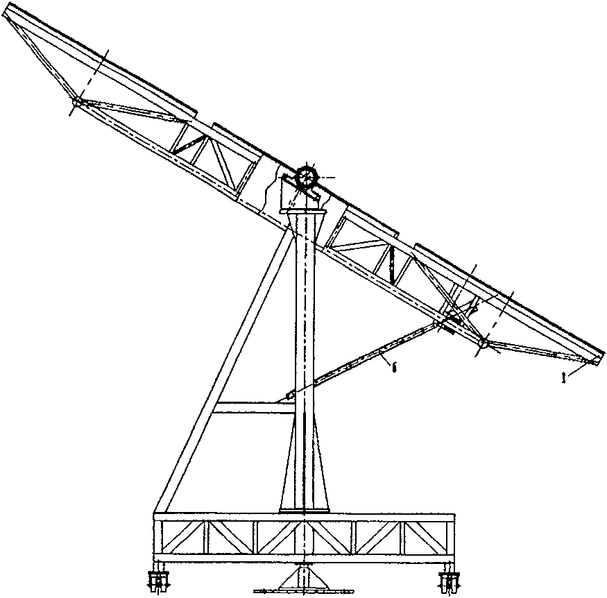
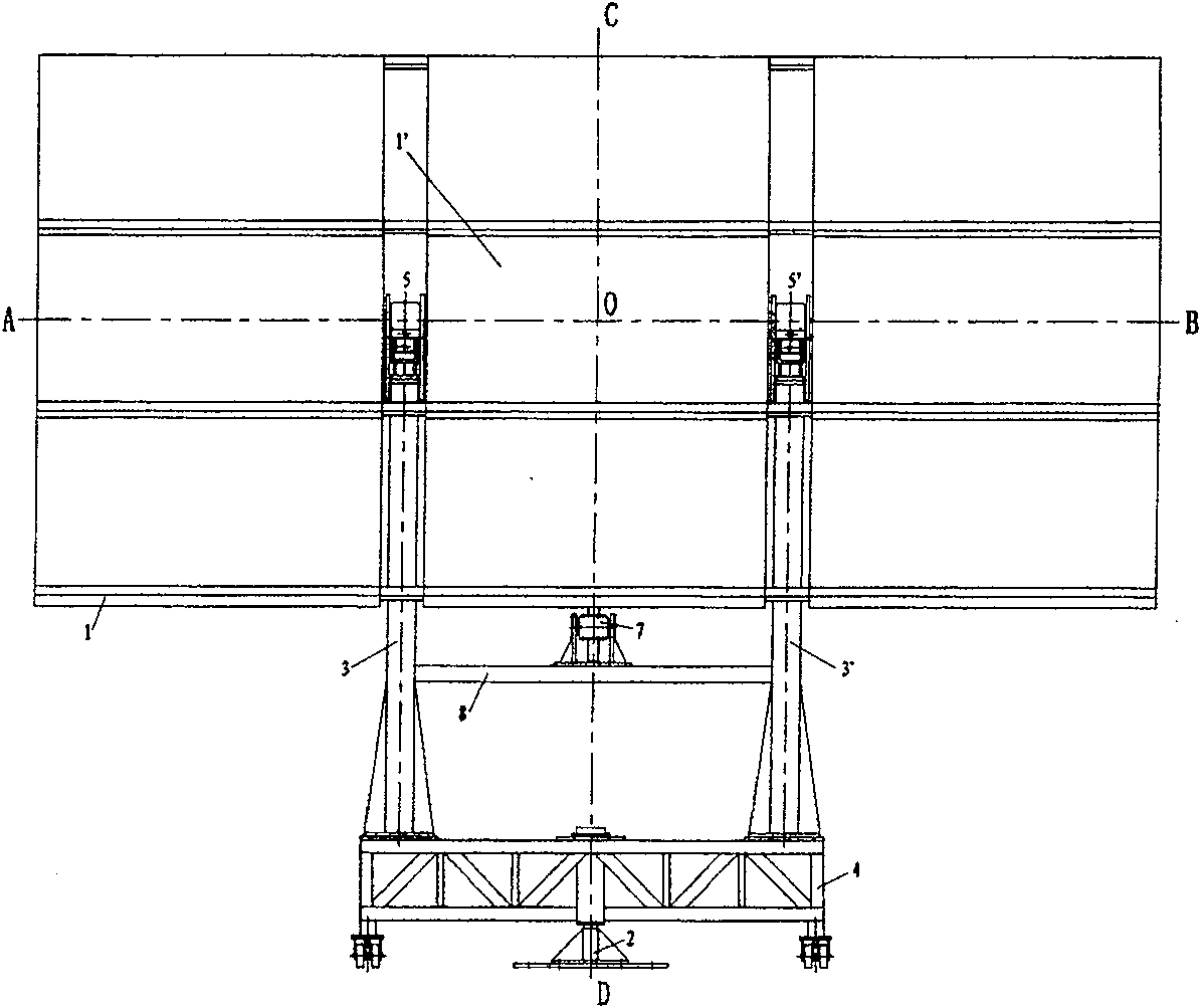
[0024] The structure of the heliostat device in this embodiment is shown as figure 1 , 2 As shown, it includes 9 pieces of plane mirrors and their overall frame 1, an elevation angle adjustment mechanism that drives the plane mirror and its overall frame 1 to rotate around the horizontal axis axis AB, and an azimuth adjustment mechanism that drives the plane mirror and its overall frame 1 to rotate around the vertical axis CD, and positioning sensors. The two axes AB and CD of the horizontal axis and the vertical axis are perpendicular to the point O in space, and the geometric center of the nine plane mirror assembly is the center of the middle plane mirror 1', which coincides with the space orthogonal point O. The central axis of the positioning sensor coincides with the line between the intersection point O of the axes of the two cross-axis mechanisms and the central point of the projection target (its specific structure will be described later).
[0025] The azimuth adj...
Embodiment 2
[0038] The basic situation of this embodiment is the same as that of Embodiment 1, the main difference is: (1) as Figure 10 , Figure 11 As shown, the overall frame 1 is limited between the two vertical frames 3, 3' of the azimuth adjustment mechanism, and two coaxial sleeves are respectively fixed on both sides of the overall frame 1, and are respectively supported by the bearing seats 5, 5' on the The upper ends of the stands 3 and 3' on both sides also keep the transverse geometric centerlines of all plane mirror assemblies coincident with the shaft sleeve axis AB, the center of all plane mirror assemblies is the center of the middle plane mirror, and the two intersecting axes perpendicular to the space rotate The intersection point O of the axes coincides. (2) The heliostat device also includes a windproof mechanism attached to the height angle adjustment mechanism of the screw nut, which is mainly composed of a set of electromagnetic clutch mechanism 18, shaft sleeve 19...
Embodiment 3
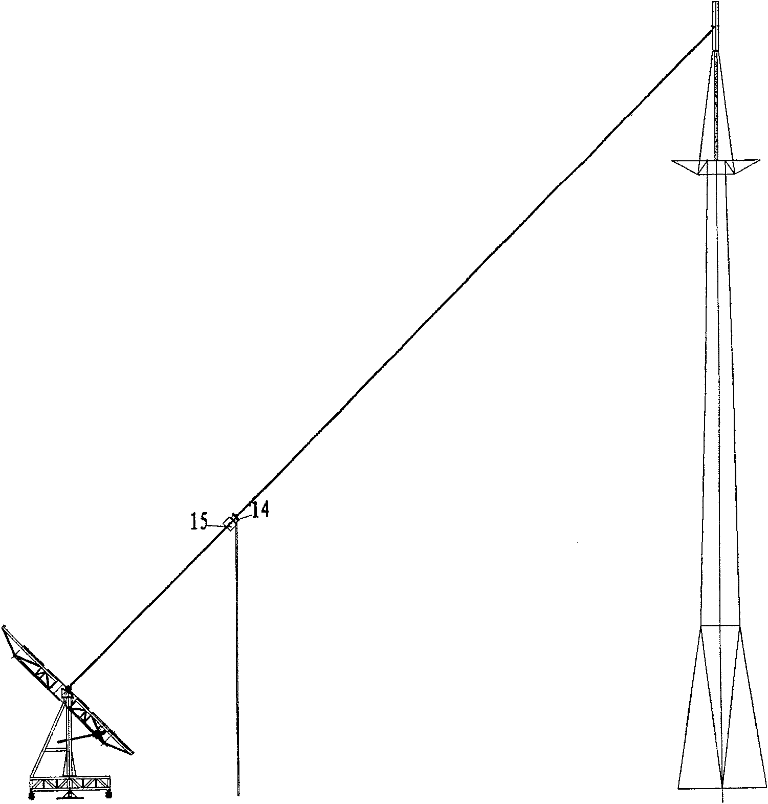
[0041] The basic situation of this embodiment is the same as that of Embodiment 2, the main difference is: Figure 12 , 13 As shown, the azimuth adjustment mechanism is not in the form of an underframe, but directly adopts a worm gear, and the worm gear shaft 14 is connected to the vertical shaft; a shaft sleeve is fixed in the middle space of the components of the overall frame 1 of the plane mirror, and the shaft sleeve is supported by the bearing seat 15 on the At the upper end of the vertical shaft 14 of the azimuth adjustment mechanism, the transverse geometric centerlines of all plane mirror assemblies coincide with the shaft sleeve axis.
[0042] The height angle adjustment mechanism still adopts the screw nut mechanism, and the centers of all plane mirror assemblies still coincide with the intersection of the two axes. Compared with Embodiments 1 and 2, although there is no plane mirror in the actual sense in the center of all plane mirror assemblies, the distance bet...
PUM
 Abstract
Description
Claims
Application Information
 - R&D
- Intellectual Property
- Life Sciences
- Materials
- Tech Scout
- Unparalleled Data Quality
- Higher Quality Content
- 60% Fewer Hallucinations
Browse by: Latest US Patents, China's latest patents, Technical Efficacy Thesaurus, Application Domain, Technology Topic, Popular Technical Reports.
© 2025 PatSnap. All rights reserved.Legal|Privacy policy|Modern Slavery Act Transparency Statement|Sitemap|About US| Contact US: help@patsnap.com