Supercharge Your Innovation With Domain-Expert AI Agents!

Cutting insert and cutting tool

A technology for cutting inserts and cutting tools, which is applied in the manufacture of tools, milling cutting inserts, transportation and packaging, etc.

Inactive Publication Date: 2009-11-04
ISCAR LTD
View PDF7 Cites 2 Cited by
  • Summary
  • Abstract
  • Description
  • Claims
  • Application Information

AI Technical Summary

Problems solved by technology

Also, there are no round cutting inserts with a radius as small as 0.5mm

Method used


Image

  • Cutting insert and cutting tool
  • Cutting insert and cutting tool
  • Cutting insert and cutting tool

Examples


Embodiment Construction

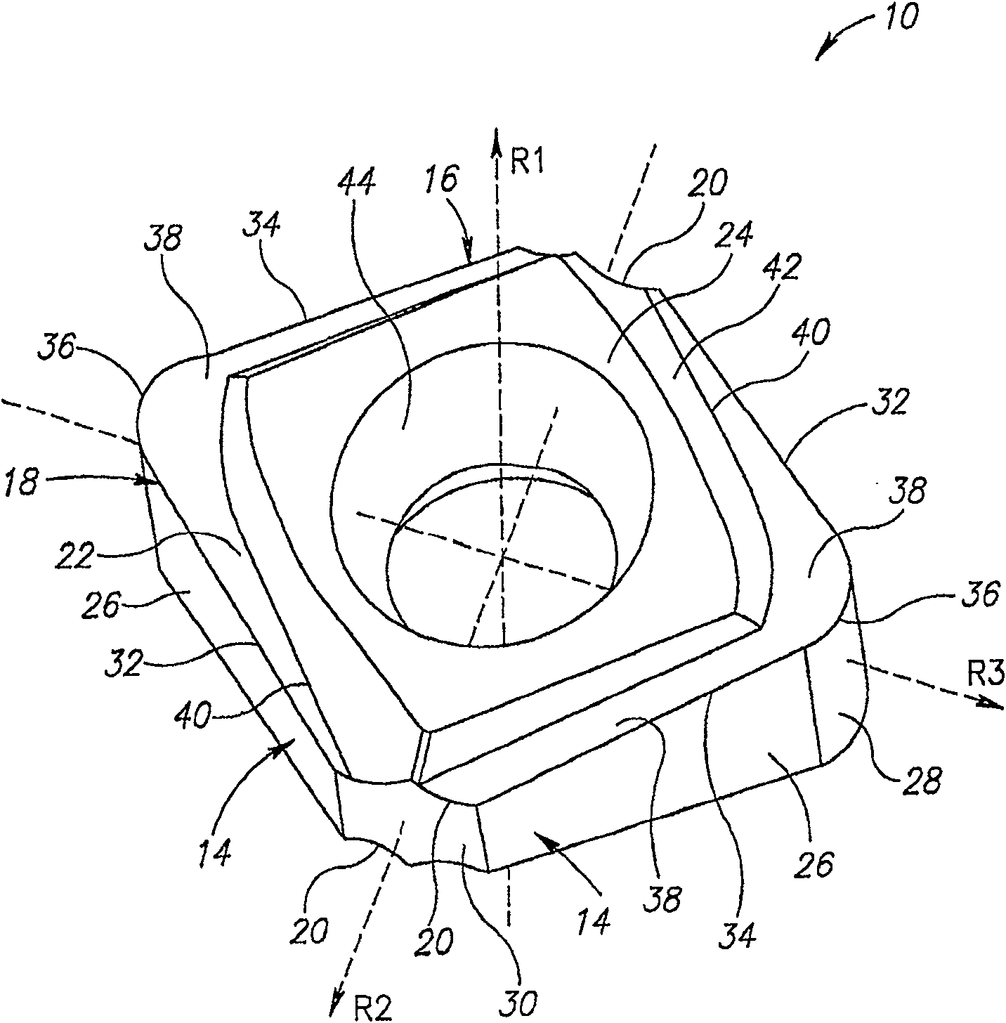
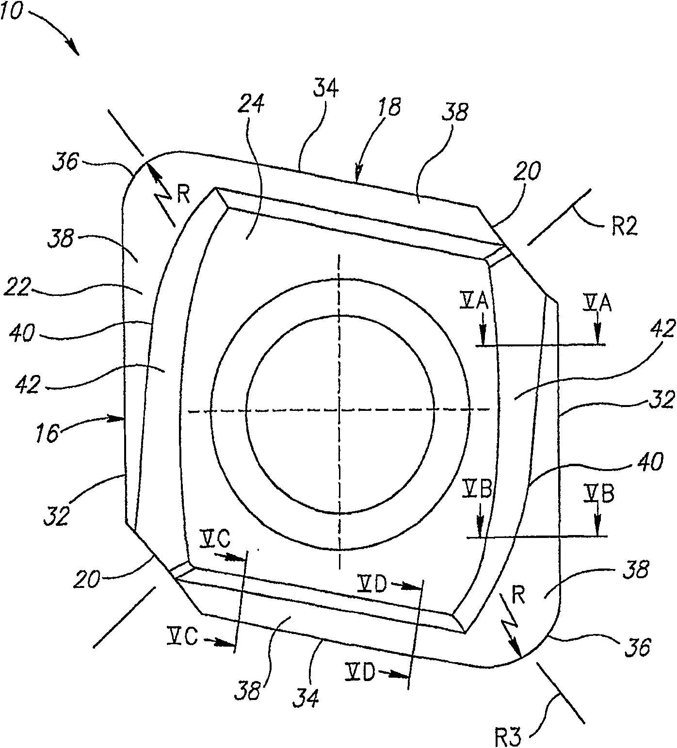
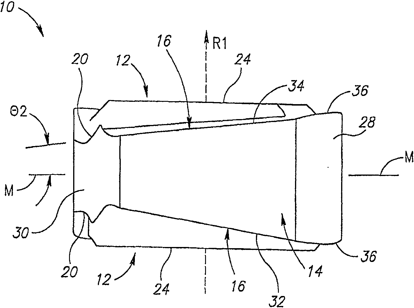
[0036] Reference is first made to the diagram representing an indexable cutting insert 10 according to the present invention. Figure 1-4 . The cutting insert 10 has two identical generally diamond-shaped end surfaces 12 with circumferential side surfaces 14 extending therethrough. Each end surface 12 adjoins a perimeter 16 where the end surface 12 and the circumferential side surface 14 merge. Each perimeter 16 includes two consecutive cutting edge segments 18 separated by two non-cutting edge segments 20 . A groove 22 adjacent a generally planar end region 24 of the end surface 12 adjoins each cutting edge segment 18 . Thus, the cutting insert 10 has two opposing flat end regions 24 . The two opposite flat end regions 24 are parallel to each other and to the plane of symmetry M of the cutting insert 10 in the middle of the flat end regions 24 .

[0037] The circumferential side surface 14 is perpendicular to the plane of symmetry M and includes eight partial side surface...


PUM


Abstract

The present invention provides a cutting insert an indexable cutting insert, for use in a cutting tool for milling operations. The cutting insert is generally rhomboidal in shape having a peripheral side surface extending between and perpendicular to the two opposing end surfaces. A cutting edge section is associated with each end surface and comprises first and second cutting edges merging at a corner cutting edge. The two first cutting edges associated with each end surface, form a non-zero first angle with respect to a median plane of the cutting insert. The peripheral side surface comprises four generally flat major side surfaces, two diametrically opposing radiused corner side surfaces, and two diametrically opposing generally flat minor side surfaces. Each end surface is provided with a flat end region. The flat end regions are parallel and form axially outermost protruding regions of the cutting insert.

Description

technical field [0001] The present invention relates to a cutting insert and cutting tool for metal cutting operations in general and for cutting small radius interior corners in particular and simultaneously for downhill cutting operations. Background technique [0002] Such cutting tools, usually in the form of face mills and shell mills, are used for metalworking in the manufacture of molds and dies and other structures with complex geometric surfaces and extended shoulders. In these applications, it is often sometimes necessary to form inner corners with small radii of less than 0.5 mm. Typically, ball nose face mills or face mills with round cutting inserts are used to form complex geometric surfaces in metal workpieces. No ball nose end mill with replaceable cutting inserts can form internal corners with a radius as small as 0.5 mm. Also, there are no round cutting inserts with a radius as small as 0.5mm. [0003] When machining a large surface of a workpiece, it is...

Claims


Application Information

Patent Timeline
Patent Type & Authority Patents(China)
IPC IPC(8): B23C5/20B23CB23C5/10
CPCB23C2210/402B23C5/109B23C2200/361B23C2200/085B23C2200/0438B23C2200/366Y10T407/1936B23C2200/125Y10T407/1962Y10T407/23B23C5/207B23C2200/246Y10T407/1924B23C2200/086B23C2200/201B23C2200/087B23C2200/0416B23C2200/326B23C5/202
Inventor A·萨特兰
Owner ISCAR LTD
Features
  • R&D
  • Intellectual Property
  • Life Sciences
  • Materials
  • Tech Scout
  • Unparalleled Data Quality
  • Higher Quality Content
  • 60% Fewer Hallucinations
Learn More