Making method of C-type ironic core of voltage mutual inductor
A technology of voltage transformer and manufacturing method, which is applied in the direction of inductance/transformer/magnet manufacturing, transformer/inductor magnetic core, circuit, etc., and can solve the problem of unifying the compactness and shape of C-shaped rectangular iron core and mass production Difficulty, difficulty in mass production and other issues, to achieve the effect of ensuring long-term safe operation, scientific and reasonable production process, and convenient installation
- Summary
- Abstract
- Description
- Claims
- Application Information
AI Technical Summary
Problems solved by technology
Method used
Image
Examples
Embodiment 1
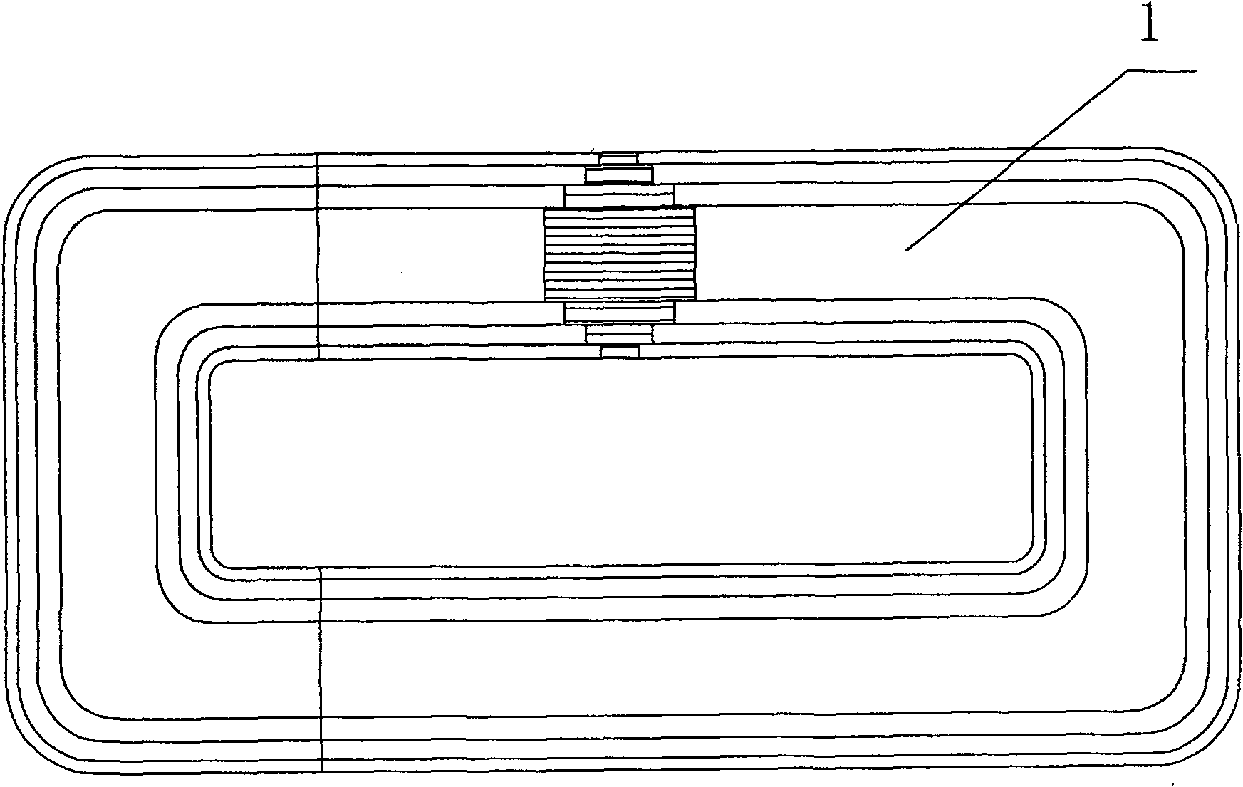
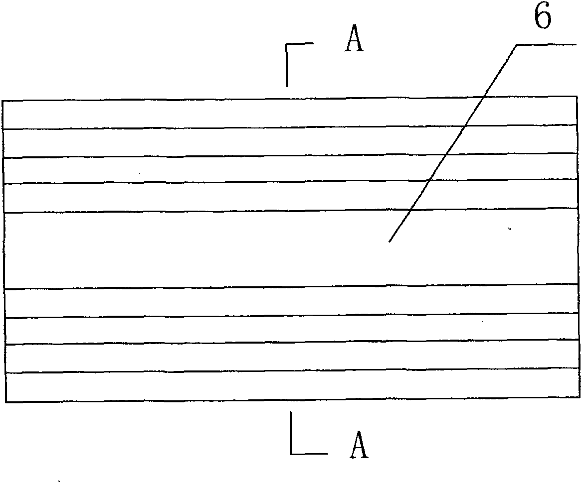
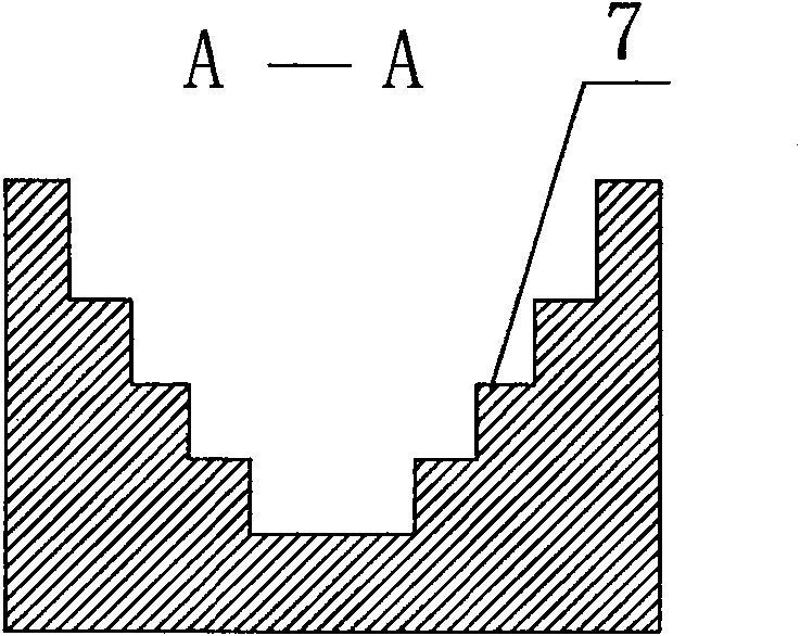
[0025] The manufacturing method of the C-type iron core of the voltage transformer, such as figure 1 As shown, firstly, according to the expanded size of the C-shaped core 1, the entire silicon steel sheet is cut into a plurality of strip-shaped silicon steel sheets with different widths, which are classified according to different widths. Calculate the number of strips that need to be used, and place the strips in grooves 6 that have the same bottom shape and the geometric shape of the side of the C-type iron core 1, as Figure 2-3 As shown, the two inner surfaces of the groove 6 are symmetrically provided with a plurality of steps 7, and the strip-shaped silicon steel sheet is from the bottom center of the groove 6 to the two inner surfaces according to the width of the strip sheet from large to small. The steps are placed upright in a symmetrical order to form a strip lamination 2, and after the strip lamination 2 is placed firmly, two clips 3 with the same shape of the in...
Embodiment 2
[0028] Embodiment 2 is basically the same as Embodiment 1, except that the whole silicon steel sheet is cut into a plurality of strip-shaped silicon steel sheets equal in width, and the strip-shaped silicon steel sheet is placed in a groove 10 upright, such as Figure 9 As shown, insert tight, stack solidly to become strip-shaped lamination 8, clamp respectively on the two ends of strip-shaped lamination 8 with two clamps 9, as Figure 10 As shown, the clamped strip laminations 8 are then placed on a U-shaped mold to be pressed into a C-shaped iron core 11, as shown in Figure 7 shown.
PUM
 Abstract
Description
Claims
Application Information
 - R&D
- Intellectual Property
- Life Sciences
- Materials
- Tech Scout
- Unparalleled Data Quality
- Higher Quality Content
- 60% Fewer Hallucinations
Browse by: Latest US Patents, China's latest patents, Technical Efficacy Thesaurus, Application Domain, Technology Topic, Popular Technical Reports.
© 2025 PatSnap. All rights reserved.Legal|Privacy policy|Modern Slavery Act Transparency Statement|Sitemap|About US| Contact US: help@patsnap.com


