Cross combined excitation mode stator and micro-ultrasonic electric machine with the same stator
An excitation method and cross-combination technology, applied in the field of ultrasonic vibration excitation stator and micro-ultrasonic motor, can solve the problems of small output torque and low work efficiency, improve no-load speed, improve work efficiency, promote practical and micro the effect of
- Summary
- Abstract
- Description
- Claims
- Application Information
AI Technical Summary
Problems solved by technology
Method used
Image
Examples
specific Embodiment approach 1
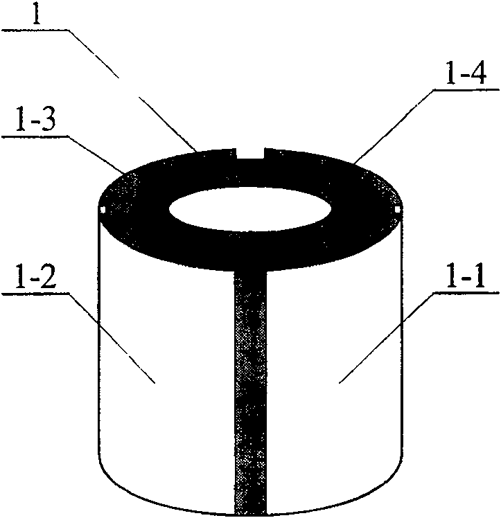
[0006] Specific implementation mode one: see Figure 3 to Figure 5 , the stator of the cross-combined excitation method provided in this specific embodiment is composed of a piezoelectric ceramic element and a stator matching block, and the outer surface of the piezoelectric ceramic element is evenly distributed with eight radial polarization for exciting vibration. external electrode.
[0007] The piezoelectric ceramic element is a piezoelectric ceramic tube, a piezoelectric ceramic column, a piezoelectric column with a conductive shaft (a metal column with a piezoelectric ceramic sheet with electrodes attached to its outer surface) or a piezoelectric tube with a conductive tube (outside A metal tube with piezoceramic sheets with electrodes attached to its surface). When the piezoelectric ceramic element is a piezoelectric ceramic tube, the polarization direction is from the outer surface of the piezoelectric ceramic tube to the inner surface of the piezoelectric ceramic tub...
specific Embodiment approach 2
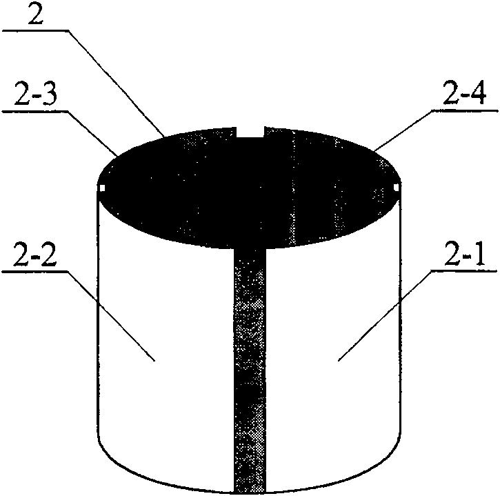
[0008] Specific implementation mode two: see image 3 with Figure 4 The present embodiment adopts the following methods to obtain the piezoelectric ceramic element with eight external electrodes: 1. Select the piezoelectric ceramic tube 3 (from the Beijing Institute of Acoustics, Chinese Academy of Sciences) that has been plated with a layer of silver film on the inner and outer surfaces after the polarization. Purchase), it adopts the radial polarization mode from the outer surface to the inner surface; 2. Divide the silver film on the surface of the above-mentioned piezoelectric ceramic tube 3 into eight parts evenly with tape strips, and then divide the inside and outside of the above-mentioned piezoelectric ceramic tube 3 The surface is all coated with anti-corrosion paint and dried, and the anti-corrosion paint is insoluble in nitric acid, such as DY-ZB-288 protective paint; 3. Tear off the tape strips on the outer surface of the piezoelectric ceramic tube 3 and put the ...
specific Embodiment approach 3
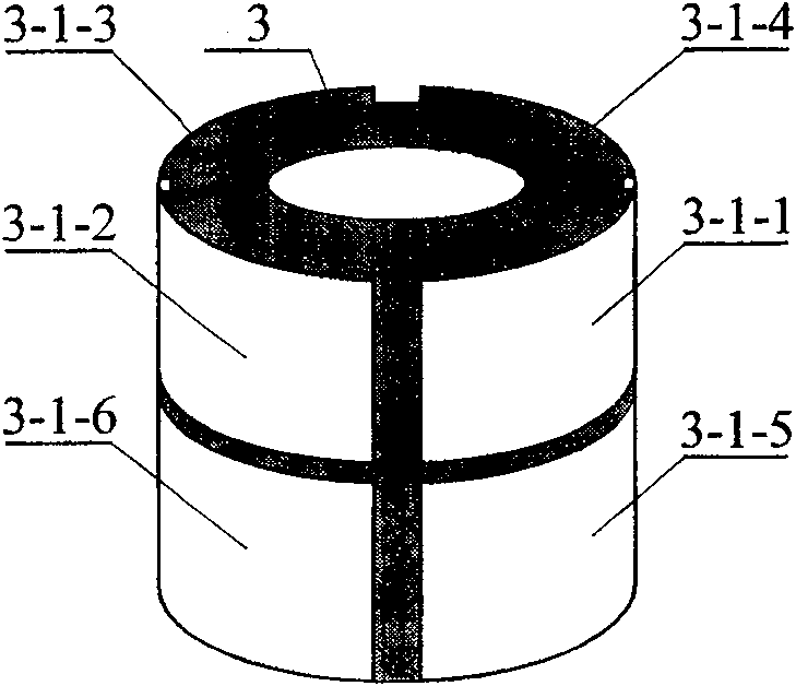
[0009] Specific implementation mode three: see Figure 5 , in this specific embodiment, the piezoelectric ceramic element with eight external electrodes is composed of a flange 11, a first piezoelectric tube 3-1 and a second piezoelectric tube 3-2, the first piezoelectric tube The outer surfaces of the electric tube 3-1 and the second piezoelectric tube 3-2 are evenly distributed with four external electrodes with the same polarization direction for exciting vibration, and the flange 11 is fixedly connected to the first piezoelectric tube 3-2. 1 and the second piezoelectric tube 3-2 and the central axes of the first piezoelectric tube 3-1 and the second piezoelectric tube 3-2 coincide, the positions of the four outer electrodes of the first piezoelectric tube 3-1 The positions of the four external electrodes of the second piezoelectric tube 3-2 are respectively set in one-to-one correspondence. When this specific embodiment is adopted, the first piezoelectric tube 3-1 and the...
PUM
 Abstract
Description
Claims
Application Information
 - R&D
- Intellectual Property
- Life Sciences
- Materials
- Tech Scout
- Unparalleled Data Quality
- Higher Quality Content
- 60% Fewer Hallucinations
Browse by: Latest US Patents, China's latest patents, Technical Efficacy Thesaurus, Application Domain, Technology Topic, Popular Technical Reports.
© 2025 PatSnap. All rights reserved.Legal|Privacy policy|Modern Slavery Act Transparency Statement|Sitemap|About US| Contact US: help@patsnap.com


