High frequency droplet ejection device and method

A technology of jetting device and jetting method, which is applied in the direction of printing device, printing, etc., can solve the problems of limiting and improving the range of frequency response, and achieve the effects of reducing the size of the tail of the droplet, improving the quality, and weakening the inaccurate displacement of the droplet

Active Publication Date: 2009-12-30
FUJIFILM DIMATIX
View PDF10 Cites 0 Cited by
  • Summary
  • Abstract
  • Description
  • Claims
  • Application Information

AI Technical Summary

Problems solved by technology

[0006] Manufacturers of droplet injectors employ various techniques to improve frequency response, however, the physical requirements of exciting droplets in drop-on-demand injectors limit the scope for improving frequency response

Method used


Image

  • High frequency droplet ejection device and method
  • High frequency droplet ejection device and method
  • High frequency droplet ejection device and method

Examples


Embodiment Construction

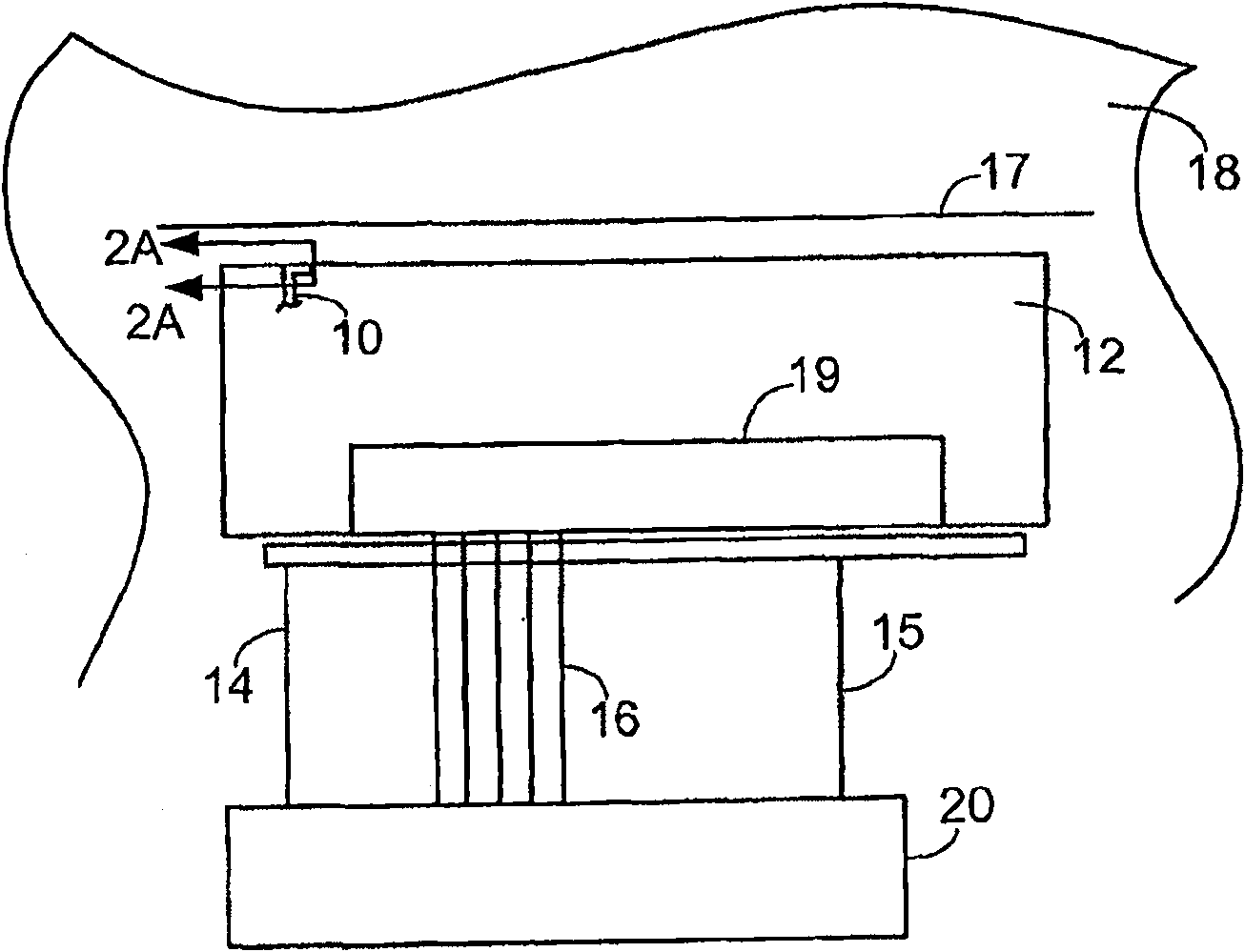
[0048] refer to figure 1 , the printhead 12 includes a plurality (for example, 128, 256 or more) of inkjet nozzles 10 (in figure 1 Only one shown in ) is driven by electrical drive pulses provided through signal lines 14 and 15 and distributed by a control circuit 19 on the board to control the ejection of the inkjet nozzles 10 . External controller 20 provides drive pulses via signal lines 14 and 15 and provides control data and logic power and timing control to board control circuit 19 via additional line 16 . Ink ejected by inkjet nozzles 10 is delivered to form one or more print lines 17 on substrate 18 moving relative to printhead 12 (eg, in the direction indicated by arrow 21 ). In some cases, the substrate 18 moves past the stationary printhead 12 in a single pass. Alternatively, the printhead may also move across the substrate 18 in a scanning state.

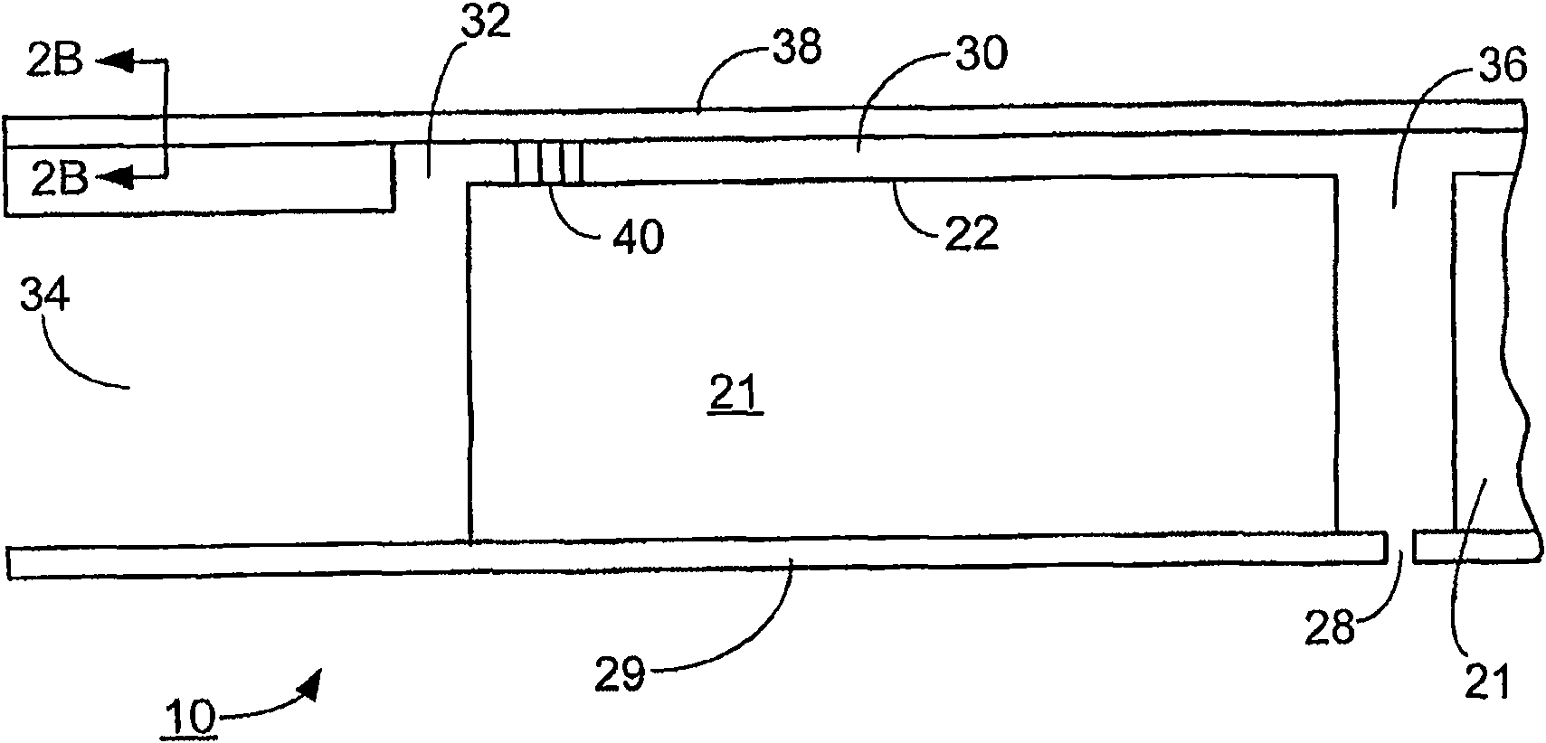
[0049] refer to Figure 2A (which is a schematic vertical cross-section), each inkjet nozzle 10 includes an elonga...


PUM


Abstract

In general, in one aspect, the invention features a method for driving a droplet ejection device having an actuator, including applying a multipulse waveform that includes two or more drive pulses to the actuator to cause the droplet ejection device to eject a single droplet of a fluid, wherein a frequency of the drive pulses is greater than a natural frequency, fj, of the droplet ejection device.

Description

technical field [0001] The present invention relates to a droplet ejection device and a method for driving the droplet ejection device. Background technique [0002] Drop ejection devices are used for a variety of purposes, most commonly for printing images on various media. The device is generally referred to as an inkjet nozzle or an inkjet printer. Drop-on-demand droplet ejection devices are used in many applications due to their flexibility and economy. Drop-on-demand devices eject a single droplet in response to a specific signal, typically an electrical wave or wave. [0003] Droplet ejection devices generally include a fluid channel from a fluid supply source to a nozzle channel. The nozzle channel ends at a nozzle opening from which droplets are ejected. The droplet ejector is controlled by applying pressure to the fluid in the fluid channel by an actuator, which may be, for example, a piezoelectric transducer, a thermal bubble generator, or an electrostatic defl...

Claims


Application Information

Patent Timeline
Patent Type & Authority Patents(China)
IPC IPC(8): B41J29/38B41J2/045
CPCB41J2/04593B41J2/04581B41J2/04595B41J2/04588B41J29/38
Inventor 罗伯特·A·哈森贝恩保罗·A·霍伊辛顿迪恩·A·加德纳史蒂文·H·巴斯
Owner FUJIFILM DIMATIX
Why Eureka
Try Eureka