Illuminating device and driving method thereof

A technology of a light-emitting device and a driving method, which is applied to lighting devices, electroluminescent light sources, light sources, etc., can solve the problems of lack of products and inconvenience.

Active Publication Date: 2010-01-06
BOE TECH GRP CO LTD
View PDF4 Cites 0 Cited by
  • Summary
  • Abstract
  • Description
  • Claims
  • Application Information

AI Technical Summary

Problems solved by technology

[0007] It can be seen that the above-mentioned existing light-emitting device and its driving method obviously still have inconvenience and defects in structure and use, and need to be further improved urgently.
In order to solve the problems existing in light-emitting devices and their driving methods, relevant manufacturers have tried their best to find solutions, but no suitable design has been developed for a long time, and general products have no suitable structure to solve the above problems. , this is obviously a problem that the relevant industry is eager to solve

Method used


Image

  • Illuminating device and driving method thereof
  • Illuminating device and driving method thereof
  • Illuminating device and driving method thereof

Examples


Embodiment Construction

[0051] In order to further explain the technical means and effects of the present invention to achieve the intended purpose of the invention, the specific implementation, structure, characteristics and methods of the light-emitting device and its driving method according to the present invention will be described below in conjunction with the accompanying drawings and preferred embodiments. Its effect is described in detail below.

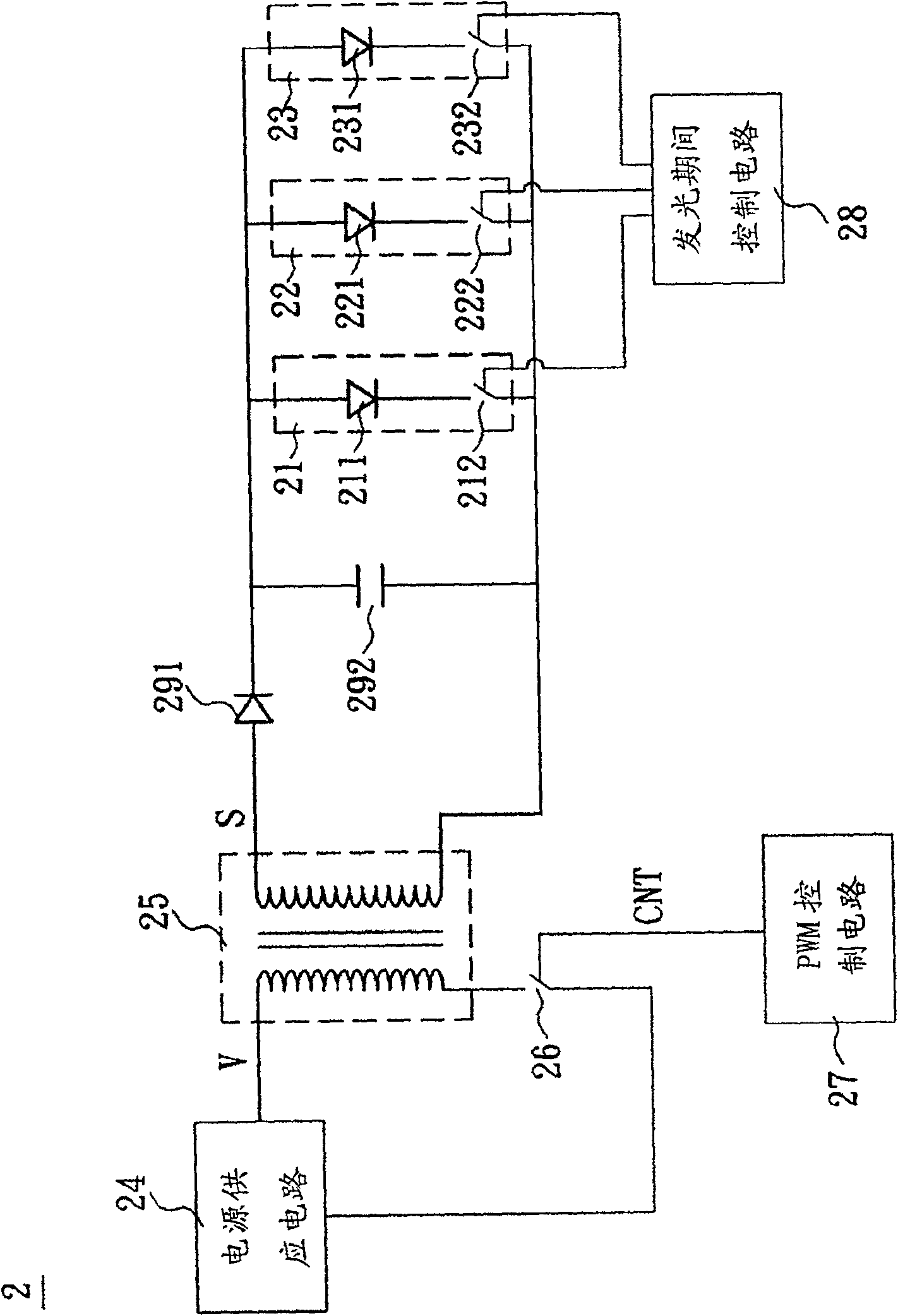
[0052] see figure 2 Shown is a schematic diagram showing a light emitting device according to a preferred embodiment of the present invention. A light emitting device 2 includes a first light emitting unit 21, a second light emitting unit 22, a third light emitting unit 23, a power supply circuit 24, a transformer 25, a transformer switch 26, a PWM control circuit 27, a light emitting period The control circuit 28 , a diode 291 , and a capacitor 292 .

[0053] The power supply circuit 24 outputs a voltage V. The transformer 25 has a primary side...


PUM


Abstract

The present invention relates to a lighting device and its driving method. The driving method separately drives a first luminous diode and a second luminous diode to light during a first period and a second period, the driving method comprises the following steps: in the first period, outputting a driving signal with a first responsibility period so as to drive the first luminous diode; and in the first period, outputting a driving signal with a second responsibility period so as to drive the first luminous diode, wherein the second responsibility period is less than the first responsibility period. The lighting device comprises: an electrical source supply circuit for outputting a voltage; a transformer with a once side and a twice side; a first lighting unit for electrical property connecting to the twice side of the transformer; a second lighting unit for electrical property connecting to the twice side of the transformer; and a transformer switch for electrical property connecting to the transformer.

Description

technical field [0001] The invention relates to a light emitting device and a driving method thereof, in particular to a light emitting device with a light emitting diode and a driving method of the light emitting device. Background technique [0002] Light-emitting diodes are generally made of P-type semiconductors and N-type semiconductors. Due to the advantages of long life, fast lighting speed, high photoelectric conversion efficiency, small size and narrow spectrum, light-emitting diodes made of semiconductor elements have recently received considerable attention. The importance of this has also accelerated the growth of light-emitting diode technology. [0003] see figure 1 Shown is a schematic diagram showing a conventional light-emitting device. A light emitting device 1 includes a power supply circuit 11, a transformer 12, a voltage stabilizing capacitor 13, a resonant filter 14, a clamper 15, a plurality of light emitting units 16-18, and a light emitting period ...

Claims


Application Information

Patent Timeline
Patent Type & Authority Patents(China)
IPC IPC(8): H05B33/08H05B44/00
Inventor 林峰立
Owner BOE TECH GRP CO LTD
Why Eureka
Try Eureka