
Light conducting plate and backlight module group

A technology of backlight module and light guide plate, which is applied in the direction of light guide, optics, optical components, etc., can solve the problems affecting the brightness and uniformity of light output of the backlight module 10, and achieve the effect of multifunctional light guide effect

Inactive Publication Date: 2010-01-20
HONG FU JIN PRECISION IND (SHENZHEN) CO LTD +1
View PDF5 Cites 0 Cited by
  • Summary
  • Abstract
  • Description
  • Claims
  • Application Information

AI Technical Summary

Problems solved by technology

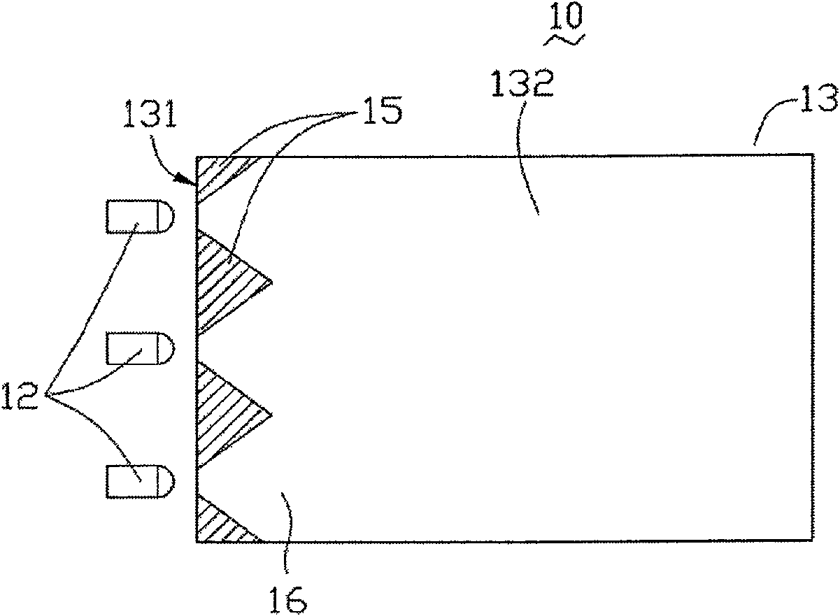
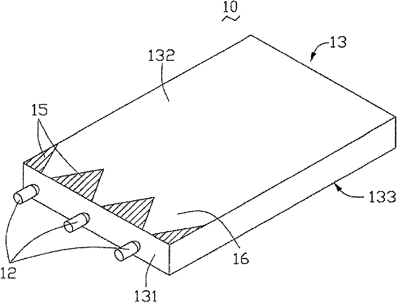
However, since the outgoing light of the light emitting diodes has a certain divergence angle, an optical dark area 15 and a light column 16 appear on the light incident surface 131 side of the light guide plate 13, and the optical dark area 15 is mainly distributed between two adjacent light emitting diodes. The light beams 16 are distributed at the position where the light guide plate 13 faces the light emitting diodes, affecting the brightness and uniformity of light output of the backlight module 10

Method used


Image

  • Light conducting plate and backlight module group
  • Light conducting plate and backlight module group
  • Light conducting plate and backlight module group

Examples


Embodiment Construction

[0021] The light guide plate and the backlight module having the light guide plate of the present technical solution will be described in detail below with reference to the accompanying drawings and multiple embodiments.

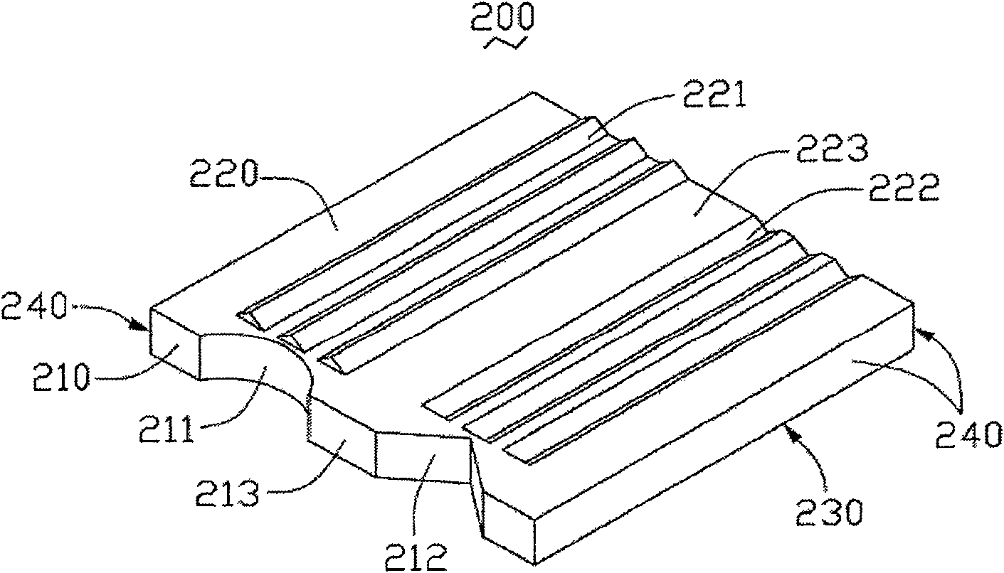
[0022] Such as image 3 and Figure 4 As shown, the first embodiment of the technical solution provides a light guide plate 200 , which includes a light incident surface 210 , a light exit surface 220 , a bottom surface 230 and a plurality of side surfaces 240 . The light incident surface 210 is used to receive the light emitted by the light source, the light exit surface 220 intersects the light incident surface 210, the bottom surface 230 is opposite to the light exit surface 220, and the plurality of side surfaces 240 are used to connect the light incident surface 210, The light emitting surface 220 and the bottom surface 230 form the overall structure of the light guide plate 200 . In this embodiment, the light emitting surface 220 is adjacent to and p...


PUM


Abstract

The invention relates to a light guide plate, comprising an incidence plane, an emergent plane crossed with the incidence plane and an undersurface opposite to the emergent plane. The incidence plane comprises at least a first groove passing through the emergent plane and the undersurface as a first light receiving region, and at least a second groove passing through the emergent plane and the undersurface as a second light receiving area. As the incidence plane forms at least two light receiving areas of different structures, different guides and adjustments of light from the same source can be realized so as to obtain different lights from the light guide plate, achieving the multi-functional light guide effect of the plate.

Description

technical field [0001] The invention relates to a light guide plate and a backlight module with the light guide plate. Background technique [0002] Since the liquid crystal itself of the liquid crystal display panel does not have light-emitting characteristics, in order to achieve the display effect, it is necessary to provide a surface light source device for the liquid crystal display panel, such as a backlight system, whose function is to supply a surface light source with sufficient brightness and uniform distribution to the liquid crystal display panel. [0003] The backlight system in the prior art is mainly composed of a light source, a light guide plate, a reflection plate, a diffuser plate and a prism plate. The light source can be arranged on one side or two opposite sides of the light guide plate and emit light beams to the light guide plate. The function of the light guide plate is to guide the light beam transmission direction, so that the light beam is unifor...

Claims


Application Information

Patent Timeline
Patent Type & Authority Patents(China)
IPC IPC(8): G02B6/00G02F1/1335
Inventor 黎瑞雍
Owner HONG FU JIN PRECISION IND (SHENZHEN) CO LTD
Learn More