Multilayer ceramic substrate and production method thereof
A technology of multilayer ceramics and manufacturing methods, which is applied in the direction of multilayer circuit manufacturing, printed circuit components, electrical components, etc., can solve the problems of difficult high-precision processing, expensive equipment, and high manufacturing costs, and achieve high reliability and flat surface High degree of precision, ensure the effect of dimensional accuracy
- Summary
- Abstract
- Description
- Claims
- Application Information
AI Technical Summary
Problems solved by technology
Method used
Image
Examples
no. 1 Embodiment approach
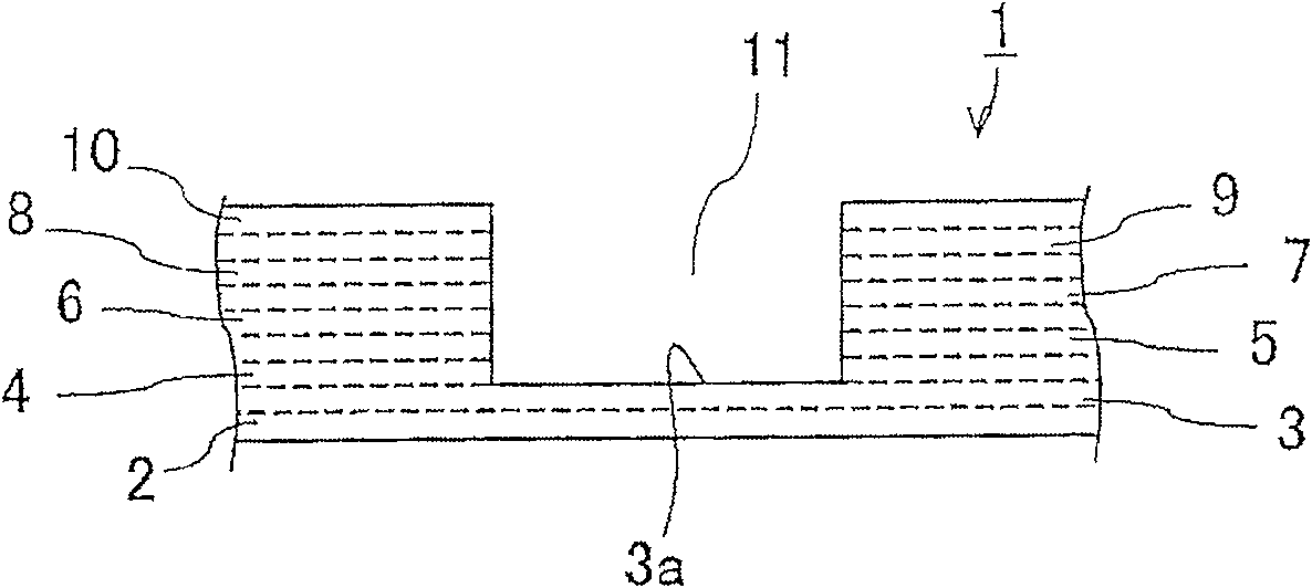
[0110] First, in this embodiment, a multilayer ceramic substrate to be manufactured will be described. In the present embodiment, the multilayer ceramic substrate to be manufactured is a multilayer ceramic substrate having a cavity (recess) for accommodating electronic components.
[0111] figure 1 It is the simplest model example showing a multilayer ceramic substrate 1 having a cavity. In this example, multilayer (here, 9 layers) ceramic layers 2 to 10 are laminated and integrated. Among these ceramic layers 2-10, the lower two layers 2, 3 are flat ceramic layers without forming through-holes for forming cavities, wherein a part of the upper surface 3a of the upper ceramic layer 3 faces the bottom of the cavity, form the bottom of the cavity.
[0112]On the other hand, the remaining ceramic layers 4 to 10 stacked on the ceramic layer 3 have through holes corresponding to the cavities, and the cavities 11 are formed as predetermined spaces by connecting these through holes....
no. 2 Embodiment approach
[0161] This embodiment is different from the above-mentioned first embodiment in that the cavity is a multi-stage cavity (in this example, a two-stage bottom cavity with a two-stage shape). Therefore, since the second-level bottom cavity is made, in addition to the first composite green sheet corresponding to the deepest bottom surface of the cavity, the second composite green sheet corresponding to the second-level bottom surface (step surface) of the cavity is equipped, and the size of the stacked through hole is Different grooving to form thin slices is a different point in the process.
[0162] In this embodiment, in the composite green sheet forming step (step S12), the Figure 10 The second composite green sheet 43 shown in (a). When producing the second composite green sheet 43, first, a third through hole that overlaps with the first through hole 24 and is larger than the first through hole 24 is provided on the ceramic green sheet 21 produced in the green sheet formi...
no. 3 Embodiment approach
[0174] For example, in the manufacturing method of the first embodiment, the layer structure of the multilayer ceramic substrate cannot achieve the balance of the upper and lower shrinkage suppression forces. Figure 15 The bottom of the cavity shown is deformed. In this case, it is only necessary to adjust the thickness of the shrinkage-inhibiting material green sheet clamping the bottom surface. This embodiment is an example of performing such adjustment.
[0175] That is, if Figure 16 As shown, the thickness of the first composite green sheet 26 in which the shrinkage-inhibiting material green sheet (first fitting sheet 25) is fitted to the cavity forming portion is adjusted. At this time, in order to correct the above-mentioned variation in thickness, the thickness of the first fitting sheet 25 may be adjusted, and the thickness of the entire first composite green sheet may be adjusted. or, as in Figure 17 As shown, the thickness of the portion corresponding to the c...
PUM
| Property | Measurement | Unit |
|---|---|---|
| thickness | aaaaa | aaaaa |
| thickness | aaaaa | aaaaa |
| thickness | aaaaa | aaaaa |
Abstract
Description
Claims
Application Information
 - R&D Engineer
- R&D Manager
- IP Professional
- Industry Leading Data Capabilities
- Powerful AI technology
- Patent DNA Extraction
Browse by: Latest US Patents, China's latest patents, Technical Efficacy Thesaurus, Application Domain, Technology Topic, Popular Technical Reports.
© 2024 PatSnap. All rights reserved.Legal|Privacy policy|Modern Slavery Act Transparency Statement|Sitemap|About US| Contact US: help@patsnap.com


