Reciprocating forced cake-unloading mechanism and method for filter cloth

A filter cloth and filter cake technology, applied in the field of filter press filter cloth unloading mechanism and method manufacturing, can solve the problems of high manufacturing cost, inability to realize automatic forced unloading of cake, complicated filter cloth walking mechanism, etc., to ensure cleanliness. Effect

Inactive Publication Date: 2010-01-27
HANGZHOU XINGYUAN FILTER TECH
View PDF3 Cites 0 Cited by
  • Summary
  • Abstract
  • Description
  • Claims
  • Application Information

AI Technical Summary

Problems solved by technology

Its disadvantages: first, the filter cloth walking mechanism is complicated, and the manufacturing cost is high; second, because the diaphragm filter cloth is in a stationary state, it is impossible to realize automatic forced cake unloading

Method used


Image

  • Reciprocating forced cake-unloading mechanism and method for filter cloth
  • Reciprocating forced cake-unloading mechanism and method for filter cloth
  • Reciprocating forced cake-unloading mechanism and method for filter cloth

Examples


Embodiment 1

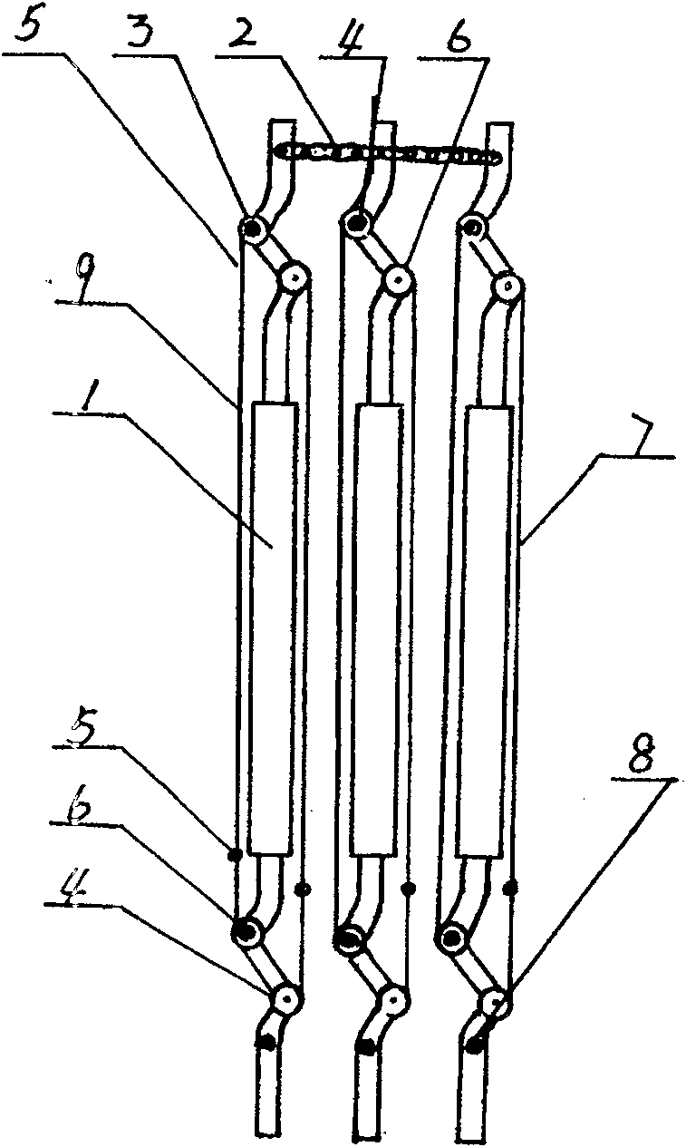
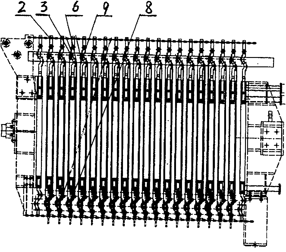
[0011] Embodiment 1: with reference to attached Figure 1~3 . The filter cloth reciprocating forced unloading mechanism, the adjacent diaphragm filter plates in the multiple diaphragm filter plates 1 located between the thrust plate and the pressing plate are connected by a circular chain 2 and driven by the pressing plate to drive multiple diaphragms The filter plate is opened or closed, the upper and lower ends of the multi-diaphragm filter plates are respectively pierced with upper and lower suspenders 4, the ends of the upper and lower suspenders 4 are equipped with sprockets 3, and the upper and lower suspenders 4 It rotates around its shaft hole or is sleeved with bearings, and the bearings are located in the lug bearing holes at the upper and lower ends of a plurality of diaphragm filter plates 1 . The upper and lower rollers 6 are respectively located on and above the upper and lower sprockets 3 and are not on the same axis. The purpose is to ensure the reliable opera...

Embodiment 2

[0012] Embodiment 2: On the basis of Embodiment 1, the filter cloth is reciprocally forced to unload the cake method, and the multiple interconnected diaphragm filter plates located between the thrust plate and the compression plate are driven by the compression plate to drive the plurality of diaphragm filters. The plates are opened one by one, and the filter cloths located on the upper and lower filter cloth rods and the diaphragm filter cloth run synchronously downwards under the drive of the moving beam and the chain wheel and chain transmission mechanism through their respective filter cloth rods. When the filter cake on the filter cloth goes down and the diaphragm When the filter plate is down, because the diaphragm filter cloth is affected by the running angle of the chain, it runs obliquely with the filter cake at an angle, and is forcibly separated from the filter cake on the diaphragm filter cloth and removed, and then the diaphragm filter cloth located on multiple dia...


PUM


Abstract

The invention is concerned with a framework and method for forced removing filtering cake. The filter cloth will remove filtering cake s to-and-fro. There are some septum filter plates locating between stop push plate and pack plate and connecting with each other driving with pack plate to open. Some septum filter clothes locating between up and down filter clothe bunch poles are respectively moved to downwards by moving beam and chain wheel chain transmission framework through filter clothe bunch poles. When filtering cake and the face of filter clothe are downwards, the filter cloth slantways moves with the filtering cake in an angle for the circulate angle of chain and removes the filtering cake in force. Then the filter clothe bunch poles of the septum filter cloth drove by moving beam will keep filter cloth to upside, meanwhile there are some muzzles spray water to clear the adjacent upward filter cloth. When the upward filter cloth moves to the right position, the flush is finish.

Description

Technical field: [0001] The invention relates to a mechanism and method for forcibly unloading filter cakes, and belongs to the field of manufacturing filter cloth cake unloading mechanisms and methods for filter presses. Background technique: [0002] Patent No. 01112254.4, titled "High-efficiency automatic filter press and filter press method", which includes electric control system (1), hydraulic system (2), frame assembly (10), filter plate assembly (9), The turning plate mechanism (56) or the liquid contact vehicle, the filter cloth walking mechanism (5) and the water flushing mechanism are characterized in that: after the short oil cylinder piston rod in the oil cylinder assembly (3) is connected with the pressing plate assembly (4), , are suspended on the top beam (29) of the frame assembly (10) through respective suspension brackets (12, 13) and move forward or backward along the top beam, and the two sides of the top of the oil cylinder assembly (3) are respectively...

Claims


Application Information

Patent Timeline
Patent Type & Authority Patents(China)
IPC IPC(8): B01D25/32
Inventor 张景陈科庆
Owner HANGZHOU XINGYUAN FILTER TECH
Why Eureka
Try Eureka