
Frame structure of two wheel motor vehicle

A technology for two-wheeled motor vehicles and vehicle body structures, which can be used in motor vehicles, machines/engines, motorcycles, etc., to solve problems such as weight increase, and to simplify the combination and connection operations, shorten piping and electrical wiring, and reduce weight. added effect

Inactive Publication Date: 2010-02-03
HONDA MOTOR CO LTD
View PDF9 Cites 0 Cited by
  • Summary
  • Abstract
  • Description
  • Claims
  • Application Information

AI Technical Summary

Problems solved by technology

However, hopefully without a significant increase in weight to achieve this

Method used


Image

  • Frame structure of two wheel motor vehicle
  • Frame structure of two wheel motor vehicle
  • Frame structure of two wheel motor vehicle

Examples


Embodiment Construction

[0050] The best way to implement the present invention will be described below with reference to the accompanying drawings. The drawings are views seen along the direction of the symbols.

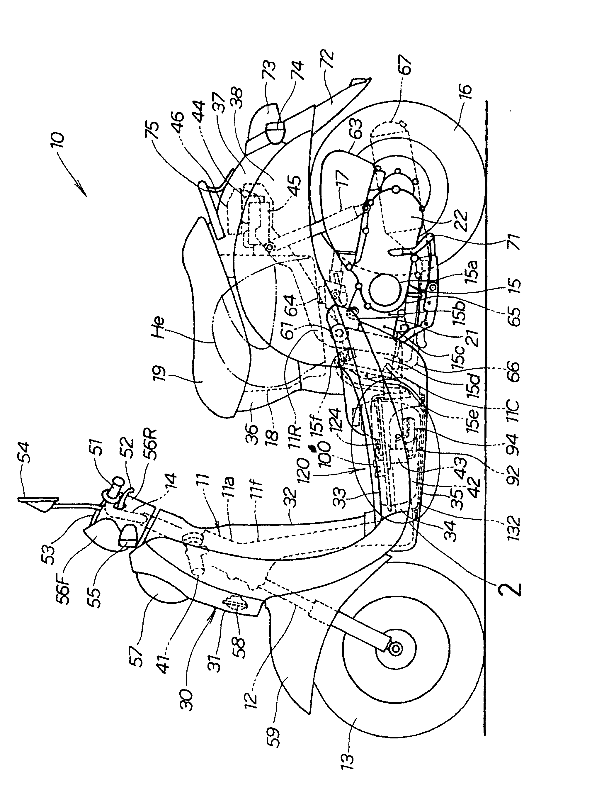
[0051] figure 1 It is a side view of the two-wheeled motor vehicle of the present invention.

[0052] The main structure of two-wheel motor vehicle 10 comprises: vehicle frame 11, the front fork 12 that is installed on the head tube 11a of vehicle frame 11, the front wheel 13 that is installed on the front fork 12, the handlebar 14 that links to each other with front fork 12, can A unit swing engine (Unit swing engine) 15 mounted on the rear of the vehicle frame 11 swinging up and down, a rear wheel 16 mounted on the unit swing engine 15, and a rear shock absorber on which the rear end of the unit swing engine 15 is suspended. Components 17, a storage box 18 installed on the rear upper part of the vehicle frame 11, and a seat 19 arranged on the storage box 18 and can be opened and closed...


PUM


Abstract

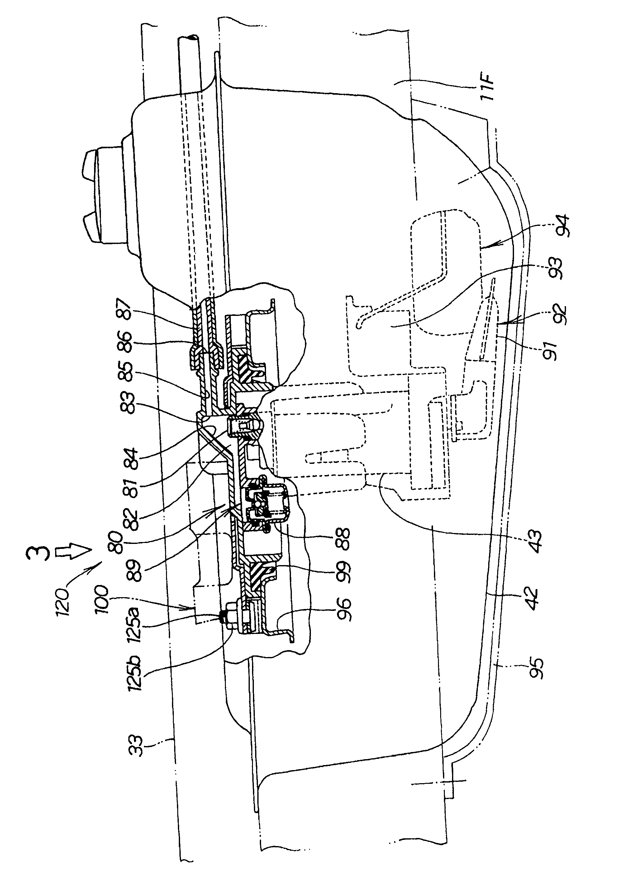
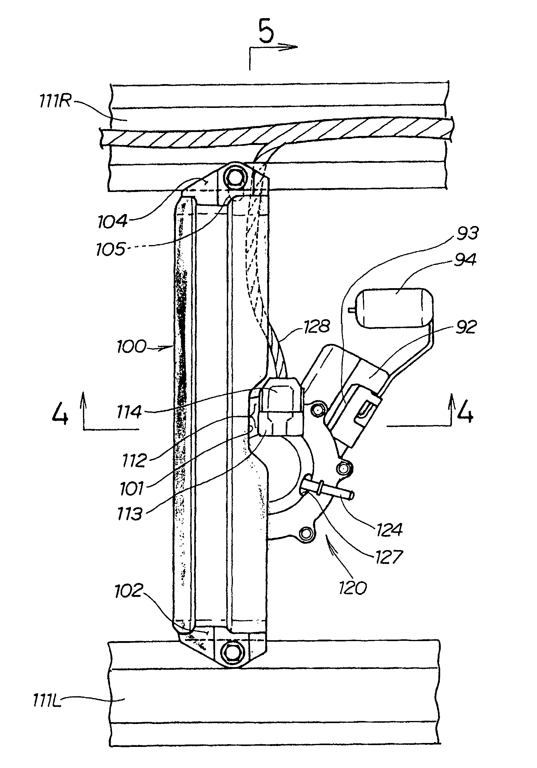
The present invention relates to a body structure capable of supporting a load of a fuel pump unit while restricting an increase in weight of a body frame. A sub-frame is present between a floor mat and a fuel pump unit. In other words, the sub-frame is mounted on a right frame and a left frame of the body frame. The sub-frame is provided with a gap in a central rear part to avoid a collision witha coupler in which a left end thereof is provided with a round hole, and a right end thereof is provided with a long hole. The left end is fastened with a bolt through the round hole to the left frame of the body frame and the right end is fastened with a bolt through the long hole to the right frame of the body frame.

Description

technical field [0001] The invention relates to a vehicle body structure of a small two-wheeled motor vehicle in which a fuel tank is arranged under a pedal and a fuel pump unit is installed in the fuel tank. Background technique [0002] In real life, there are various small two-wheeled vehicles in which a fuel tank is provided under a footboard and a fuel pump unit is housed in the fuel tank. [0003] Conventionally, a small two-wheeled vehicle in which a fuel tank is installed near a pedal has been disclosed (for example, refer to Patent Document 1). [0004] Patent Document 1: Japanese Unexamined Publication No. 2003-120450 ( image 3 ). [0005] Patent Document 1 will be described based on the following drawings. [0006] Figure 13 It is a diagram explaining the basic structure of the prior art. The fuel tank 302 is placed on the left and right frames 301 and 301 of the vehicle frame, the fuel pump unit 303 is built in the fuel tank 302, and the fuel pump unit 303 a...

Claims


Application Information

Patent Timeline
Patent Type & Authority Patents(China)
IPC IPC(8): B62J35/00B62J37/00B62J25/00B62K11/02B62J99/00F02M37/04
Inventor 林秀树乾秀二郎八木泽胜一
Owner HONDA MOTOR CO LTD
Learn More