
Power unit suspension gear for minitype motorcycle type vehicle

A technology for power units and suspension devices, which is applied to power units, motorcycles, vehicle parts, etc., can solve the problems of increased number of parts, increased cost, complex structure, etc., to reduce the number of parts and simplify the structure , the effect of large vibration

Inactive Publication Date: 2010-02-03
HONDA MOTOR CO LTD
View PDF9 Cites 0 Cited by
  • Summary
  • Abstract
  • Description
  • Claims
  • Application Information

AI Technical Summary

Problems solved by technology

[0007] In the above-mentioned vehicle, since the mechanism for restricting the movement of the power unit 3 in the vertical direction is arranged on the first link 21, the mechanism for restricting the movement of the power unit 3 in the front-rear direction is straddled between the first link 21 and the first link 21. At the same time, the second link 31 is composed of different mechanisms. Therefore, while the number of parts increases, the structure also becomes complicated, resulting in an increase in cost.

Method used


Image

  • Power unit suspension gear for minitype motorcycle type vehicle
  • Power unit suspension gear for minitype motorcycle type vehicle
  • Power unit suspension gear for minitype motorcycle type vehicle

Examples


Embodiment Construction

[0100] Hereinafter, the best mode for carrying out the present invention will be described with reference to the drawings. In addition, the drawings are obtained while looking at the reference numerals.

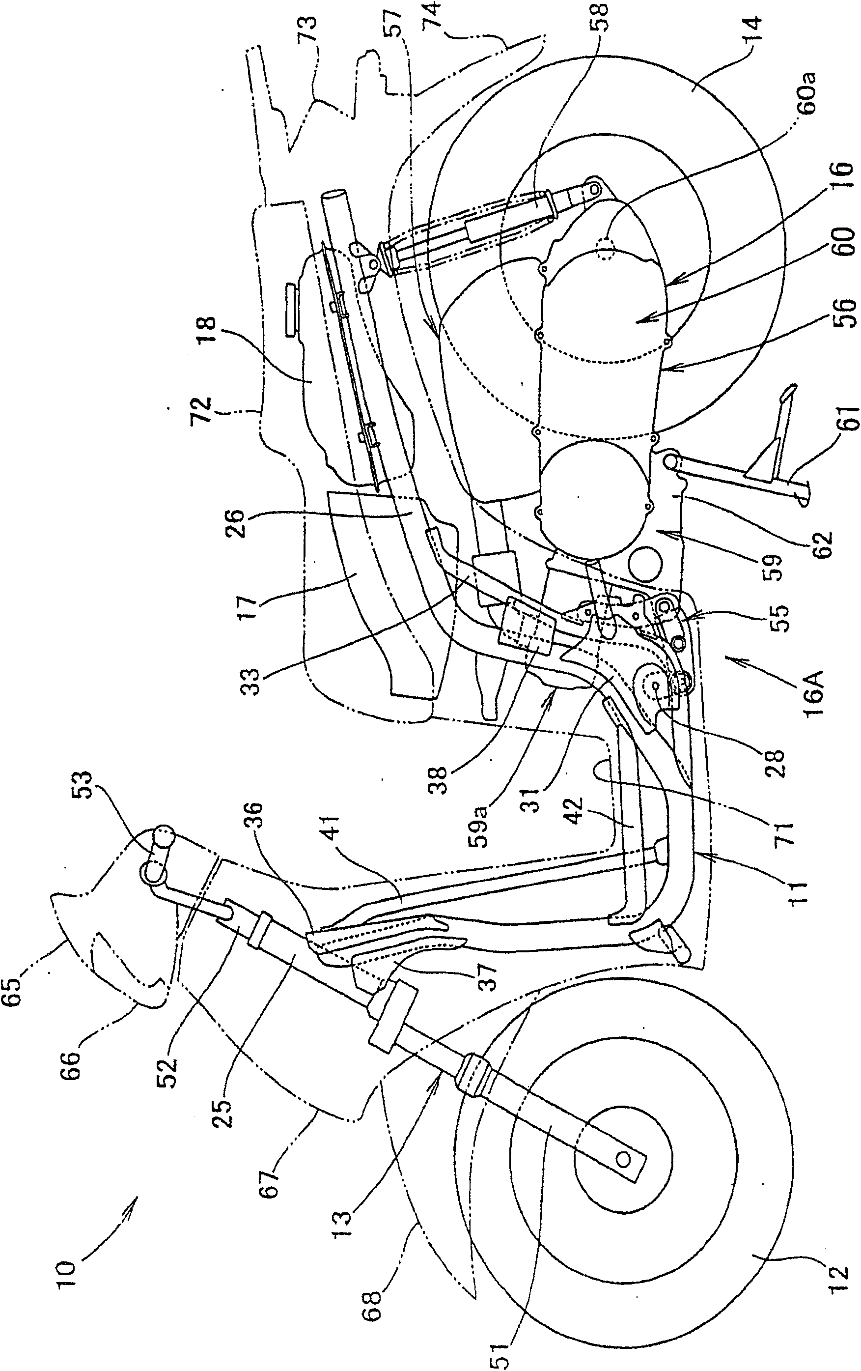
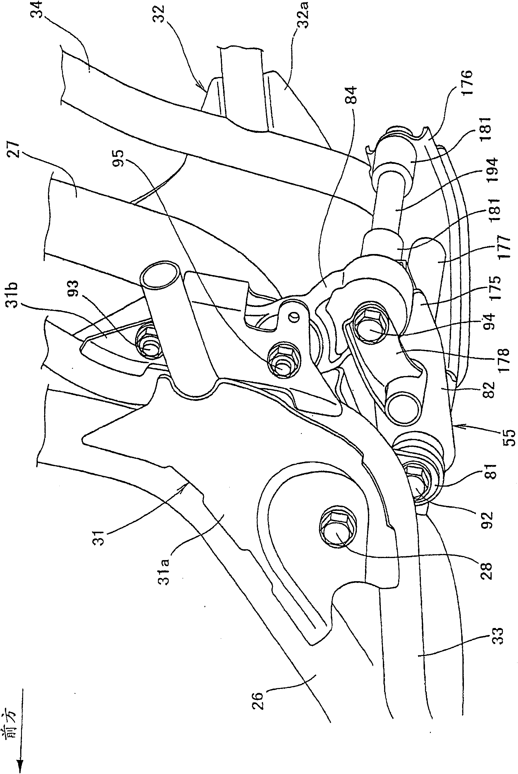
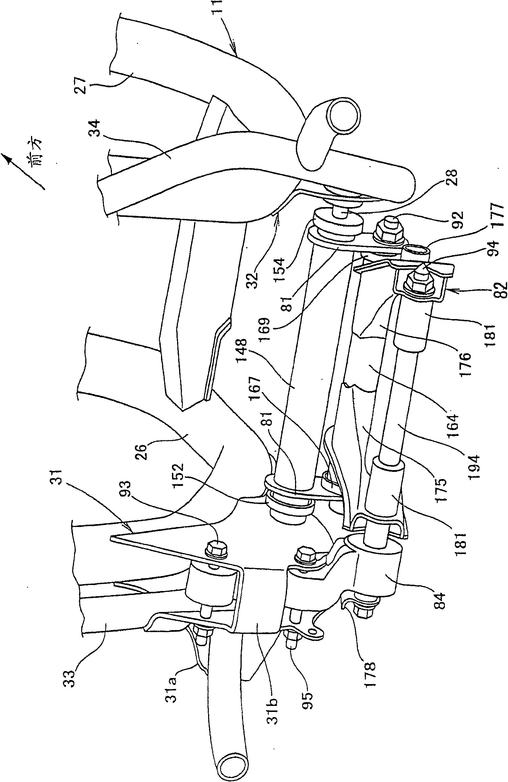
[0101] figure 1It is a side view (first embodiment) of a scooter-type vehicle having a power unit suspension device of the present invention. The scooter-type vehicle 10 includes: a vehicle frame 11 serving as a skeleton; It is arranged on the front part of the vehicle frame 11 for suspending and steering the front wheels 12; the rear wheel suspension driving mechanism 16 is connected to the substantially central part of the vehicle frame 11 for suspending and steering the rear wheels 14. drive; and the storage box 17 and the fuel tank 18 installed on the rear upper part of the vehicle frame 11.

[0102] The vehicle frame 11 includes: a front pipe 25 disposed at the front end; a pair of left and right main frames 26, 27 (only the reference number 26 on the near front side i...


PUM


Abstract

The present invention provides a power unit suspension device for minitype motorcycle type vehicle, the device can simplify the structure of limit device which is used for limiting the move along up and down direction of power unit and rear wheel. Fix one end of the connecting bar (84) on the inner pintle board (31b) and the bar can swing freely, fix the power unit (56) on the other end of the connecting bar (84) and the power unit can swing freely, limit mechanism (105) is set on the inner pintle board (31b) and the connecting bar (84), for limiting the move along front and back direction ofpower unit (56), and making the line segment where the third pintle (93) on the connecting bar (84) connects the fourth pintle (94), at the same time, the connecting bar (84) supports the fourth pintle (94) by rubber bush (112).

Description

technical field [0001] The present invention relates to an improvement in the suspension arrangement of a power unit of a scooter type vehicle. Background technique [0002] As a conventional power unit suspension device for a scooter vehicle, a structure in which a power unit is connected to a vehicle body via a link mechanism is known (for example, refer to Patent Document 1). [0003] Patent Document 1: Japanese Patent Application Laid-Open No. Sho 62-120288. [0004] Hereinafter, FIG. 6 of Patent Document 1 will be described. [0005] One end of the first connecting rod 21 is installed on the main frame 8 through the support shaft 14 to swing freely up and down, and one end of the second connecting rod 31 is connected to the other end of the first connecting rod 21 through the support shaft 38 to swing freely. The vehicle body part (power unit) 3 is swingably connected to the other end of the second connecting rod 31 by a bolt 42 . [0006] The length direction of the...

Claims


Application Information

Patent Timeline
Patent Type & Authority Patents(China)
IPC IPC(8): B62M7/04B60K5/00
Inventor 道坂进铃木孝志相原顺二佐佐木典彦林秀树
Owner HONDA MOTOR CO LTD
Learn More