Hydraulic drive device for working machine

A technology for working machines and driving devices, applied in mechanical equipment, machines/engines, engine working fluids, etc., can solve problems such as energy consumption, poor fuel consumption rate, inability to obtain pump absorption power, etc., to reduce fuel costs, eliminate The effect of fuel consumption

Active Publication Date: 2010-02-03
KOMATSU LTD
View PDF8 Cites 2 Cited by
  • Summary
  • Abstract
  • Description
  • Claims
  • Application Information

AI Technical Summary

Problems solved by technology

[0008] However, in the work performed by a hydraulic excavator, for example, when excavating earth and sand, the excavated earth and sand are pocketed into a bucket, the boom is lifted and the upper rotating body is rotated, thereby accumulating the earth and sand in the bucket to a dump truck. In the above case, the required engine output and pump output are very different from the case where the accumulation of soil and sand is completed and the boom is lowered and rotated to move to the next operation cycle.
[0009] However, in the hydraulic drive device of Patent Document 1, there is a problem that when the heavy excavation mode is selected such as Figure 11 When performing the above-mentioned series of operations in the state shown in (a), it cannot be used according to the changing contents of the work in the series of operations or the operation amount of the control lever, etc., in other words, it cannot be used according to changes in the working conditions. Engine output and pump output vary, so wasteful energy is consumed due to operating conditions
[0010] In addition, in the hydraulic drive device of the above-mentioned patent document 2, there is the following problem: when performing the above-mentioned series of operations, if Figure 11 As shown in (c), although unnecessary energy consumption is suppressed by limiting the output power of the pump according to changes in operating conditions, in this series of operations, the engine is on the adjustment line Ra (engine speed NA to Nd). Operating within the range, always in a state of poor fuel consumption rate, resulting in unnecessary fuel consumption
[0011] Additionally, if Figure 11 As shown in (b) and (c) respectively, there is still the following problem: if the output torque of the engine and the absorption torque of the hydraulic pump are matched at the matching points Mc and Md on the adjustment lines Rc and Ra, the The deviation of the absorption torque characteristics of the hydraulic pump (the line width ΔQ indicated by the two-dot chain line in the figure) caused by problems in the manufacture of the hydraulic pump, etc. is proportional to the deviation of the pump absorption power (the power absorbed by the hydraulic pump from the engine) Also remarkably, the desired pump absorbed power cannot be obtained, and workability cannot be ensured satisfactorily.

Method used


Image

  • Hydraulic drive device for working machine
  • Hydraulic drive device for working machine
  • Hydraulic drive device for working machine

Examples


no. 1 approach

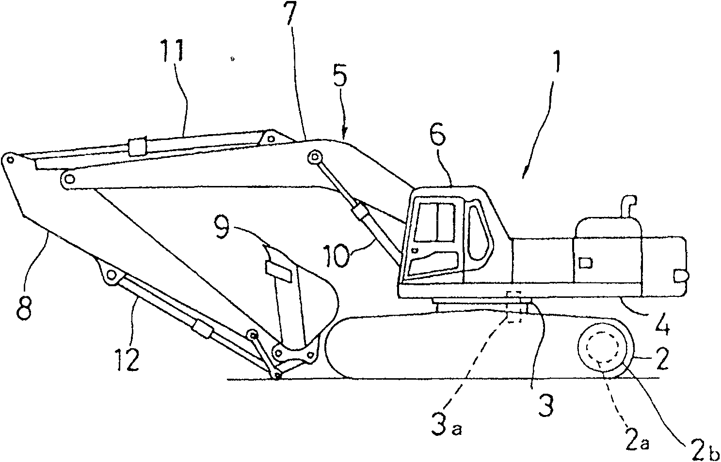
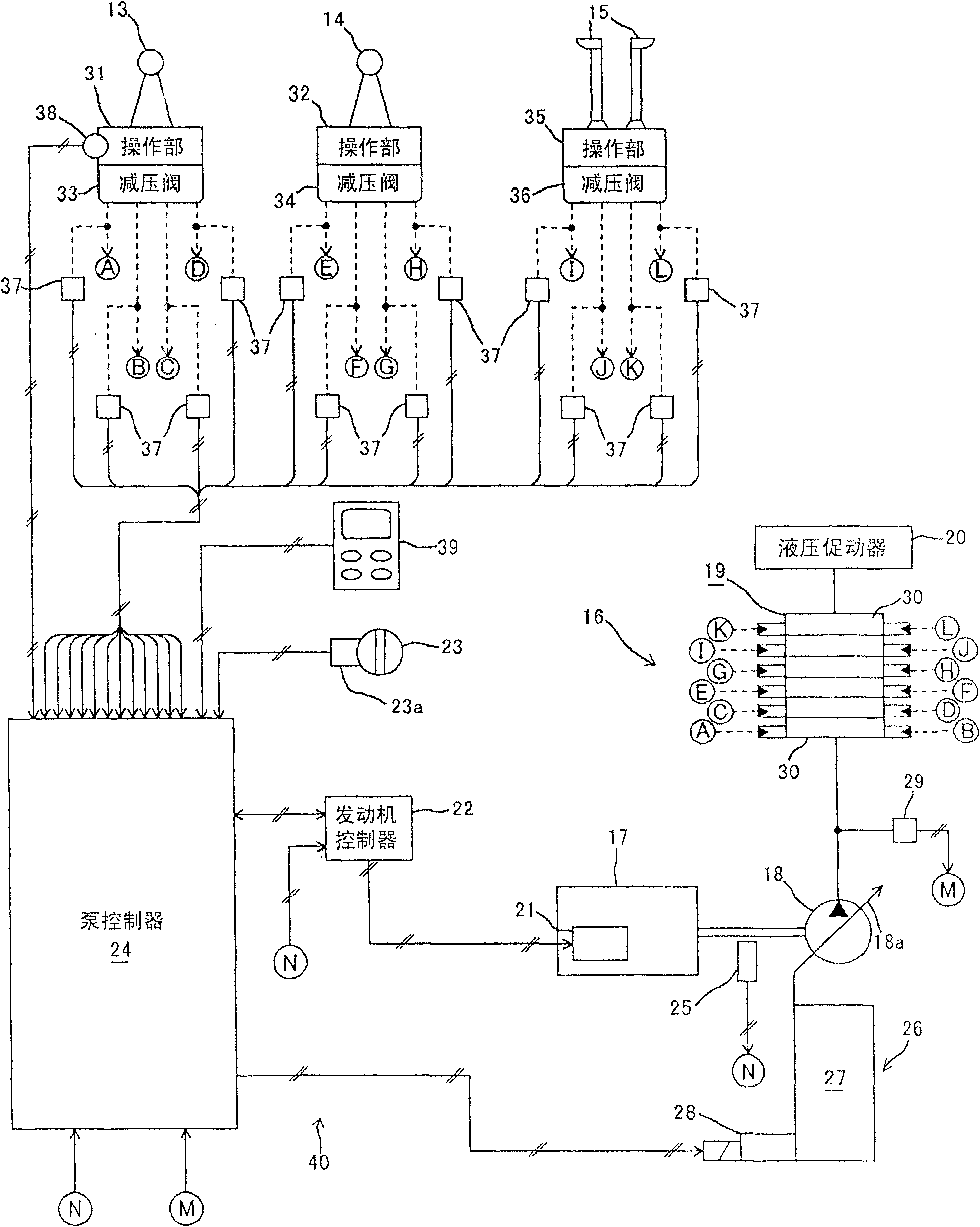
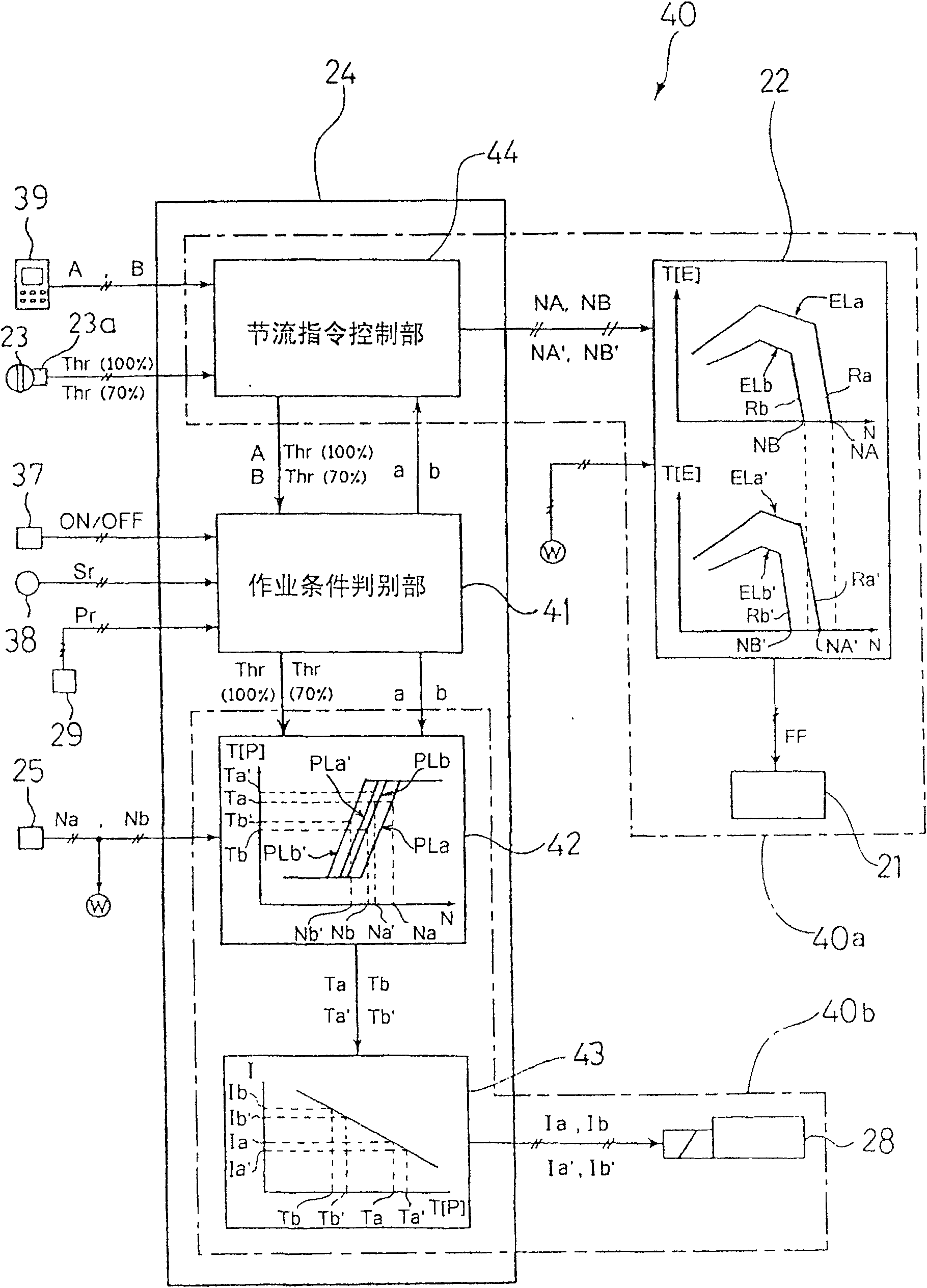
[0048] figure 1 A side view showing a hydraulic excavator according to a first embodiment of the present invention. in addition, figure 2It is an overall schematic system configuration diagram showing the hydraulic drive device of the first embodiment. in addition, image 3 A functional block diagram showing the engine-hydraulic pump control device of the first embodiment.

[0049] Such as figure 1 As shown, the hydraulic excavator of the present embodiment is provided with: an undercarriage body 2 constituted by a traveling device 2b driven by a traveling hydraulic motor 2a; a swivel device 3 driven by a swivel hydraulic motor 3a; The upper revolving body 4 arranged on the lower traveling body 2 ; the working machine 5 installed at the front center of the upper revolving body 4 ; and the cab 6 provided at the front left of the upper revolving body 4 . Here, the working machine 5 is sequentially connected to a boom 7, an arm 8, and a bucket 9 from the side of the uppe...

no. 2 approach

[0099] Next, a second embodiment of the present invention will be described. Figure 9 It is a characteristic diagram showing the relationship between the engine output torque and the hydraulic pump absorption torque in the second embodiment. in addition, Figure 10 It shows a figure explaining the variation suppression effect of the pump absorption power of 2nd Embodiment. Compared with the first embodiment, this embodiment is only different in the relationship between the output torque characteristics of the engine 17 and the absorption torque characteristics of the hydraulic pump 18, and is basically the same as the first embodiment in other respects. Since they are the same, the following description will focus on the differences from the first embodiment.

[0100] In this embodiment, when the working condition discriminated by the working condition judging unit 41 is the working condition (a), as in Figure 9 and Figure 10 As shown, the engine output torque character...


PUM


Abstract

The first object is to provide a hydraulic drive device for a working machine, capable of optimally controlling pump absorption horsepower according to change in working condition, thereby reducing fuel consumption. The second object is to provide, on the basis of the first object, to provide a hydraulic drive device for a working machine, capable of suppressing variation in pump absorption horsepower. When working condition determined by a working condition determining section (41) is changed, for example, from working condition (a) to working condition (b), an engine output torque characteristics line (ELa) is switched to an engine output torque characteristics line (ELb) by an engine control device (40a), and a hydraulic pump absorption torque characteristics line (PLa) is switched to ahydraulic pump absorption torque characteristics line (PLb) by a hydraulic pump control device (40b). Further, output torque of an engine (17) and absorption torque of a hydraulic pump (18) are matched to each other at output torque points (Ma, Mb) at which the output of the engine (17) is maximum.

Description

technical field [0001] The invention relates to a hydraulic drive device suitable for being mounted on working machines such as hydraulic excavators. Background technique [0002] As well known, such conventional hydraulic drive devices are disclosed in Patent Documents 1 and 2, for example. In the hydraulic drive device of Patent Document 1, the output torque characteristics of the engine and the absorption torque characteristics of the hydraulic pump are respectively set to suit the work mode selected by the operator. On the other hand, in the hydraulic drive device of Patent Document 2, by detecting a specific operation state of the operation control lever, it is detected that the working machine is in a specific operating state, and when the working machine is in a specific operating state, the corresponding In the operating state, the maximum value of the absorption torque of the hydraulic pump is set to a predetermined value. [0003] Patent Document 1: Japanese Pate...

Claims


Application Information

Patent Timeline
Patent Type & Authority Patents(China)
IPC IPC(8): E02F9/22F04B49/06F04B17/05
CPCF04B17/05E02F9/2235F04B49/065E02F9/2246B60W2510/305F04B49/06E02F9/226F04B2201/1202F04B2203/0603F05B2270/335F05B2210/11Y10S417/00
Inventor 成濑真己
Owner KOMATSU LTD
Why Eureka
Try Eureka