Image forming apparatus

Active Publication Date: 2011-05-26
KYOCERA DOCUMENT SOLUTIONS INC
View PDF4 Cites 9 Cited by
  • Summary
  • Abstract
  • Description
  • Claims
  • Application Information

AI Technical Summary

Benefits of technology

[0012]According to this aspect, it is possible to eliminate the wasteful power consumption due to the needless heating of the non-sheet passing region. Further, even when the size of the paper sheet used for the subsequent print job after the completion o

Problems solved by technology

However, in a case where the heating width remains changed until a print job is completed, the temperature drops in the non-sheet passing region of the rotary member.
This leads to a problem that a user needs to wait because of being unable to execute a print job immediately after completion of the preceding print job.
However, under such control, the non-sheet passing region that does not need to be heated is actively heated, which poses a problem of wasteful power c

Method used


Image

  • Image forming apparatus
  • Image forming apparatus
  • Image forming apparatus

Examples


Example

[0025]Hereinafter, with reference to FIGS. 1 to 9, a first embodiment of the present invention is described by taking a multifunction peripheral 100 (corresponding to an image forming apparatus) as an example. However, components, layouts, and other such elements described in each embodiment do not limit the scope of the invention and are mere examples used for the description.

[0026](Schematic Structure of Multifunction Peripheral 100)

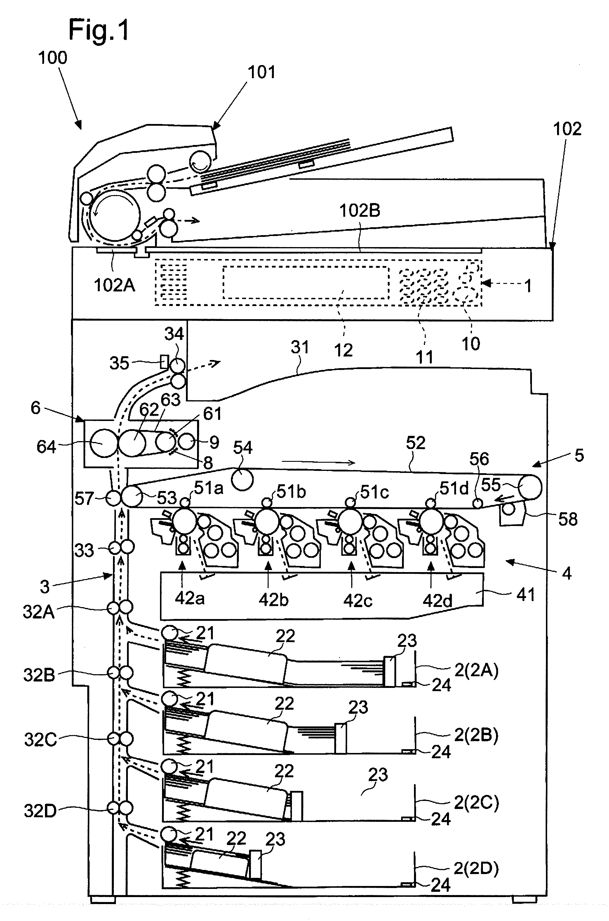
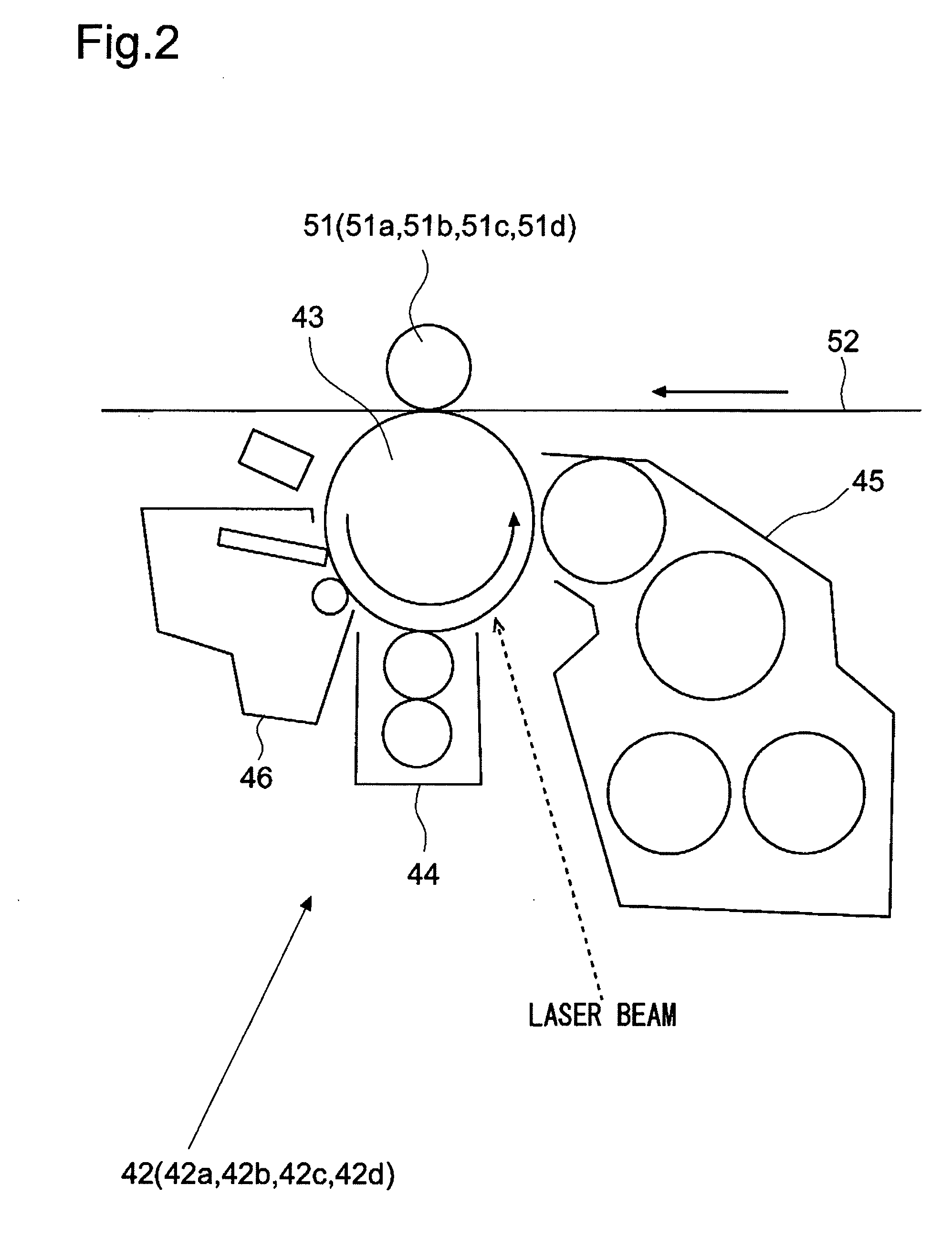
[0027]First, FIGS. 1 and 2 are used to describe an outline of the multifunction peripheral 100 according to the first embodiment of the present invention. FIG. 1 is a schematic sectional view illustrating the schematic structure of the multifunction peripheral 100 according to the first embodiment of the present invention. FIG. 2 is an enlarged schematic sectional view of one image forming unit 42 according to the first embodiment of the present invention.

[0028]First, an document transporting apparatus 101 for automatically and successively transportin...

Example

Second Embodiment

[0122]Next, FIGS. 10 and 11 are referenced to describe a multifunction peripheral 100 according to a second embodiment of the present invention. FIG. 10 is a flowchart illustrating an example of a flow of heating control performed on the fixing device 6 at execution of the print job according to the second embodiment of the present invention. FIG. 11 is an explanatory diagram illustrating an example of measurement data on a temperature rising rate obtained from the multifunction peripheral 100 according to the second embodiment of the present invention.

[0123]Note that, the second embodiment is different from the first embodiment in that the timing to widen the heating width W is determined at the execution of the print job based on the temperature rising rate for the non-sheet passing region which is measured on the multifunction peripheral 100. However, the other components may be the same as those of the first embodiment, and description of the common components i...


PUM


Abstract

Provided is an image forming apparatus, including: a heating section; a coil that is opposed to the heating section, for heating the heating section; a core that has a circumferential surface covered with a magnetic shielding plate having different lengths in an axis direction in a plurality of steps according to a position in a circumferential direction; a rotary section for causing the core to rotate; a plurality of temperature sensing elements for sensing temperatures of the heating section; and a control section for controlling a heating width by controlling the rotary section to control a rotation angle of the core, setting the heating width corresponding to a size of a paper sheet at a start of a print job, and setting the heating width wider than at the start of the print job midway through the print job.

Description

[0001]This application is based upon and claims the benefit of priority from the corresponding Japanese Patent Application No. 2009-269011 filed on Nov. 26, 2009, the entire contents of which are incorporated herein by reference.BACKGROUND OF THE INVENTION[0002]1. Field of the Invention[0003]The present invention relates to an image forming apparatus which uses induction heating to heat a paper sheet onto which a toner image has been transferred and fix the toner image thereto, such as a multifunction peripheral, a copier, a printer, or a FAX machine.[0004]2. Description of Related Art[0005]Up to now, in some image forming apparatuses such as a multifunction peripheral, a formed toner image is transferred onto a paper sheet and fixed thereto by heat. A fixing device for fixing the toner image includes a rotary member such as a roller in order to perform heating while transporting the paper sheet. Some fixing devices fix the toner image by generating Joule heat by an eddy current due...

Claims


Application Information

Patent Timeline
IPC IPC(8): G03G15/20
CPCG03G15/2039
Inventor YODA, JUNYA
Owner KYOCERA DOCUMENT SOLUTIONS INC
Why Eureka
Try Eureka