Flash device, camera device and method and program thereof for the elimination of wasteful power consumption therein

a technology of flash device and power supply battery, which is applied in the field of flash device and camera device with flash device, can solve the problems of limiting the power supply capacity that can be secured, waste of electric power from the battery, and unrealistic, and achieves the effect of extending the life of the power supply battery and avoiding wasteful power consumption

Inactive Publication Date: 2005-03-24
CASIO COMPUTER CO LTD
View PDF7 Cites 9 Cited by
  • Summary
  • Abstract
  • Description
  • Claims
  • Application Information

AI Technical Summary

Benefits of technology

The present invention has been attained in view of the problems heretofore posed, and its object is to provide a flash device, a camera device with the flash device, and a method and program thereof which can eliminate wasteful power consumption and extend a life of a power supply battery.

Problems solved by technology

wherein C is the capacitance of the main capacitor and V is the charging voltage, and electric power for this is wasted from the battery.
On the other hand, a prolonged battery life (continuous use time per battery change or charging) is required in recent digital cameras owing to increased capacity of storage media to be used and corresponding increase in the number of images that can be stored and increase in time of picking up moving images, but there is naturally a limit in power supply capacity that can be secured in order to maintain a reduced size, reduced weight and design diversity of an apparatus.
Therefore, it has been a challenge to find ways to eliminate wasteful power consumption in the strobe described above.
This can be achieved if the strobe light is not available for emission all the time, which is not realistic due to inconvenience caused thereby.

Method used


Image

  • Flash device, camera device and method and program thereof for the elimination of wasteful power consumption therein
  • Flash device, camera device and method and program thereof for the elimination of wasteful power consumption therein
  • Flash device, camera device and method and program thereof for the elimination of wasteful power consumption therein

Examples


Embodiment Construction

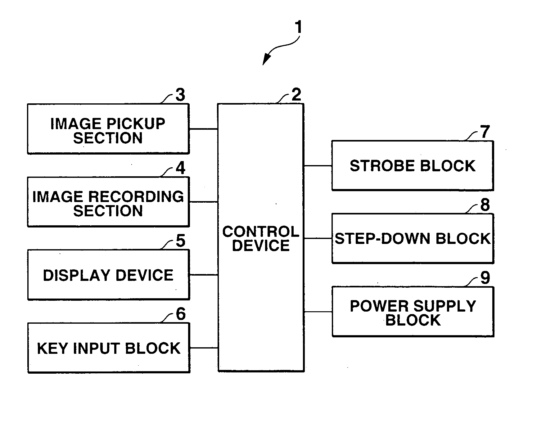
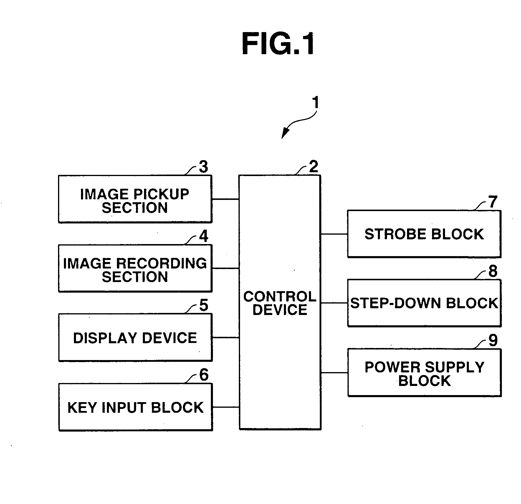
One embodiment of the present invention will hereinafter be described in accordance with the drawings. FIG. 1 is a block diagram showing a schematic configuration of a digital camera 1 according to the present invention.

The digital camera 1 is constituted of a control device 2, and an image pickup section 3, an image recording section 4, a display device 5, a key input block 6, a strobe block 7, a step-down block 8 and a power supply block 9 whose operations are controlled by the control device. In the present embodiment, the control device 2, the strobe block 7, the step-down block 8 and the power supply block 9 actualize a flash device of the present invention.

The control device 2 has a ROM storing a predetermined program and a RAM for working, and is a microcomputer comprising various kinds of digital signal processing functions including data compression and decompression. The control device 2 operates in accordance with the program stored in the ROM to function as control ...


PUM


Abstract

In a REC mode of an ordinary image pickup standby state, a main capacitor is connected to a side of a step-up/charging circuit via a switch, and the main capacitor is charged with electric power of a charging battery. When the REC mode is changed to other modes, the main capacitor is connected to a side of a step-down circuit by a switching operation of the switch. The step-down circuit steps down charging voltage of the main capacitor to 4.2 V to supply it to a power supply circuit of a camera, and steps down the charging voltage to 5 V to supply it to the charging battery which is a power supply of the camera. When it is no longer necessary to emit fill light, the electric power lost from the main capacitor due to natural discharge can automatically be utilized efficiently for operations other than the emission of the fill light.

Description

BACKGROUND OF THE INVENTION 1. Field of the Invention The present invention relates to a flash device, a camera device with the flash device, and a method and program thereof. 2. Description of the Related Art Recently, digital cameras have generally become widespread which use a solid-state image sensing device of a CCD type or MOS type to image a subject and store it as image data in a storage medium such as a flash memory. Most of such digital cameras are equipped with strobes (flash devices) similar to those of conventional cameras. The strobe built in a camera is configured to step up a voltage of a battery stored in a camera main body, as is well known, and charge a main capacitor with the voltage, and at the time of picking up an image, it gives a charge stored in the main capacitor to a discharge tube (such as a xenon tube) via a trigger coil in accordance with a trigger signal, so as to discharge it to emit light. In addition, a capacitance of the main capacitor is abo...

Claims


Application Information

Patent Timeline
Patent Type & Authority Applications(United States)
IPC IPC(8): G03B15/05G03B15/03G03B17/02H04N5/225H04N5/238H05B41/32
CPCH04N5/2256H05B41/32H04N5/23241H04N23/56H04N23/651H05B41/30
Inventor YUYAMA, MASAMI
Owner CASIO COMPUTER CO LTD
Why Eureka
Try Eureka