Biological fusion type foot joint rehabilitation robot

A technology for rehabilitation robots and foot joints, which is used in manipulators, gymnastics equipment, physical therapy, etc., can solve problems such as poor safety, poor efficacy, and few degrees of freedom, and achieve the effects of good adaptation, simple and novel structure, and flexible movement.

Inactive Publication Date: 2010-02-10
YANSHAN UNIV
View PDF4 Cites 3 Cited by
  • Summary
  • Abstract
  • Description
  • Claims
  • Application Information

AI Technical Summary

Problems solved by technology

[0008] The common disadvantage of these rehabilitation device systems is that the special complexity of human limbs was not fully considered at the beginning of the design, and the physiological and anatomical structure of human limbs was not taken as the center of design, so that the system rehabilitation movement form is single, the degree of freedom is small, and the mechanism system lacks flexibility.
Therefore, it cannot well solve the problem of limited movement funct...

Method used


Image

  • Biological fusion type foot joint rehabilitation robot
  • Biological fusion type foot joint rehabilitation robot
  • Biological fusion type foot joint rehabilitation robot

Examples


Embodiment 1

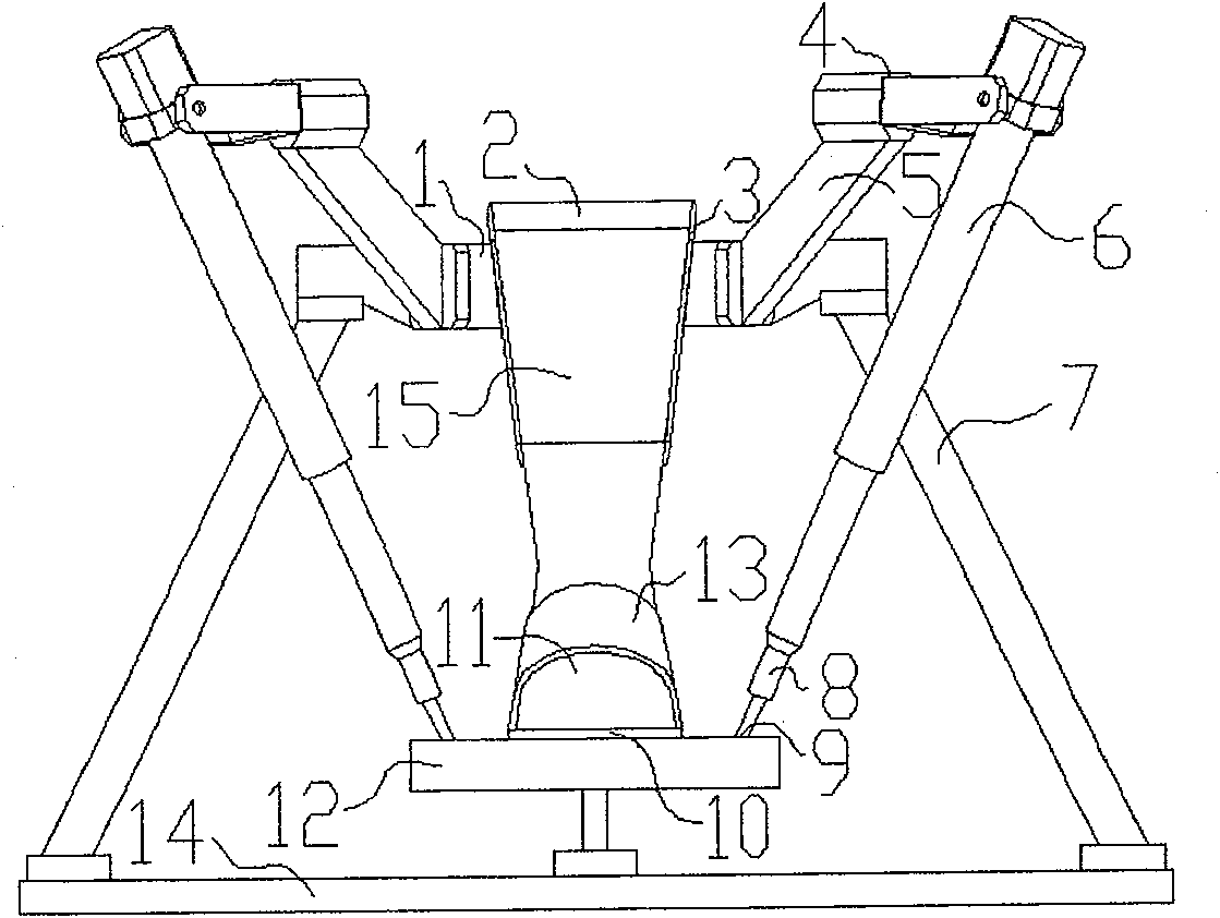
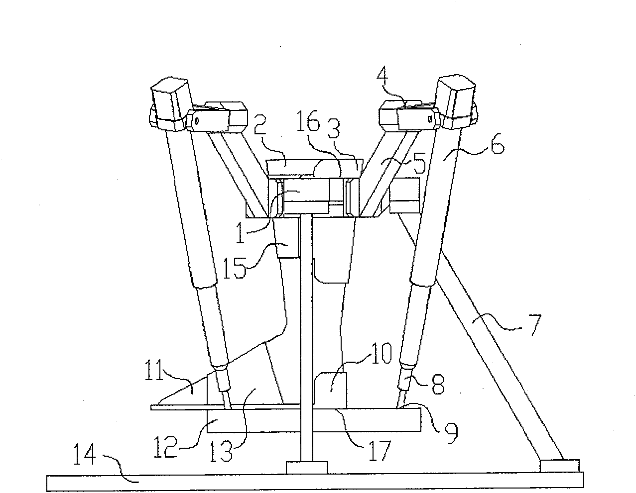
[0027] figure 1 It is an embodiment disclosed by the present invention. The upper ends of the four linear drive units are connected to the upper platform mounting bracket 5 through the U pair (universal hinge) 4, and the lower ends are connected to the lower platform 17 through the S pair (spherical hinge) 9, and the human feet 11 are fixed to the lower platform 17 through the clamp. Joint, shank 2 links to each other with upper platform 16 by shank fixer. The hasp II 15 is fixedly connected with the fixed plate 3 , and the four mounting brackets 5 and the fixed plate 3 are fixedly connected to the mounting platform 1 to form an upper platform 16 . After the rear part of the lower leg is put into the fixing plate, the lower leg is fixed to the upper platform 16 by the hasp 13 at the front part. Hasp I 13 is fixedly installed with pedal 10, and pedal 10 is fixedly connected on platform 12 and forms lower platform 17. The sole of the people's feet is put into the pedal 10, an...

Embodiment 2

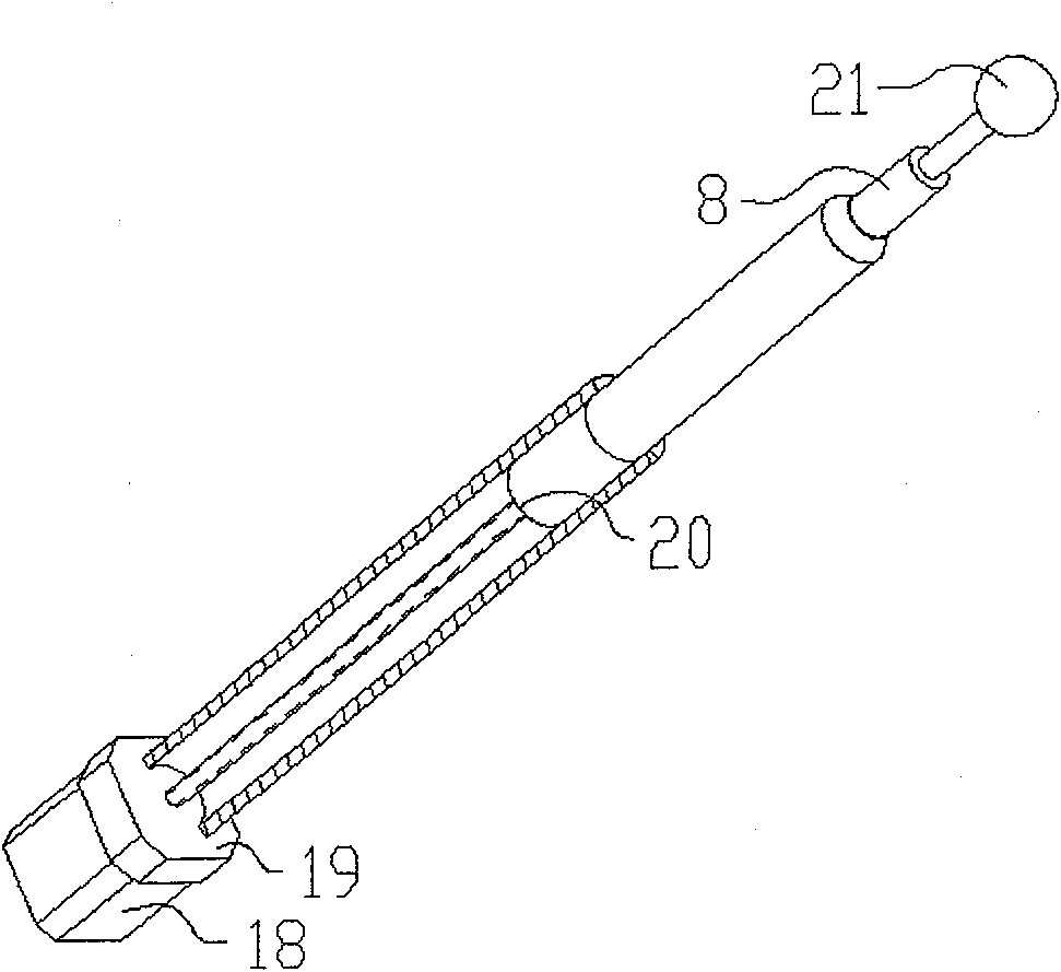
[0029] Figure 6 It is the second embodiment of the present invention. Replace the linear driver in Example 1 with a two-way motion cylinder 22. The two-way motion cylinder 22 is composed of a cylinder body and a plunger rod. The elastic coupling unit 8 is connected in series with the plunger rod. The upper end of the elastic coupling unit 8 is connected to the ball pair. Cooperating ball head 21 . The connection mode between the two-way motion cylinder 22 and the mechanical system of the robot is the same as that in Embodiment 1. The air source 24 supplies air to the cylinder through the pipeline 25 to realize the reciprocating motion of the linear drive unit.

Embodiment 3

[0031] Figure 7 It is the third embodiment of the present invention. The linear driver in Example 1 is replaced by an electric cylinder 23. The electric cylinder 23 is composed of a cylinder body and a rod. The elastic coupling unit 8 is connected in series with the rod. The upper end of the elastic coupling unit 8 is a ball head that matches the ball pair. 21. The connection mode between the electric cylinder 23 and the mechanical system of the robot is the same as that in Embodiment 1. The reciprocating motion of the linear drive unit is achieved by applying power to the electric cylinder.


PUM


Abstract

The invention relates to a biology fusion foot joint return robot, which is characterized in that: the upper ends of four straight drivers are connected to the mounting support (5) of upper platform (16) via universal hinge (4), while the lower ends via ball couples (9) are connected to the lower platform (12); feet (11) via clamper are connected to the lower platform (12); the leg (2) via fixer is connected to the upper platform (16); the straight driver (6) can be lead screw nut device, bidirectional movable cylinder (22) or electric cylinder (33). The invention is based on bionic technique,to fuse the under-knee part of human as branch into system. The invention has several freedoms, to realize complex return movements, while the rotation hinge point is layered with feet joint rotationhinge point. And the data can be used in diagnosis.

Description

technical field [0001] The invention relates to a rehabilitation robot system, in particular to a foot joint rehabilitation robot which has multiple degrees of freedom, can realize joint function rehabilitation in all directions, and has a rotation hinge point completely coincident with a foot joint rotation hinge point. Background technique [0002] The foot joints include the supratalar joint (commonly known as the ankle joint), and the subtalar joint (including the talar navicular joint and the talar heel joint). The supratalar joint is a pulley joint, and its main movements are dorsiflexion and plantarflexion. In addition, because the trochlear joint is wide in front and narrow in the rear, when the foot is in plantar flexion, the narrow posterior part of the trochlear enters the glenoid fossa, making the glenoid fossa larger than the joint head, so it can also perform mild abduction and adduction movements. The subtalar joint is functionally a joint joint, and its main...

Claims


Application Information

Patent Timeline
IPC IPC(8): A61H1/02A63B23/08A63B23/04B25J11/00
Inventor 赵铁石潘旺李艳文梁志成
Owner YANSHAN UNIV
Why Eureka
Try Eureka