
Apparatus for depositing atomic layer using gas separation type showerhead

A technology of atomic layer deposition and gas separation, applied in coatings, electrical components, gaseous chemical plating, etc., can solve problems such as reduced plasma efficiency

Inactive Publication Date: 2010-02-17
WONIK IPS CO LTD
View PDF3 Cites 2 Cited by
  • Summary
  • Abstract
  • Description
  • Claims
  • Application Information

AI Technical Summary

Problems solved by technology

However, in this case, when the ionized precursor is supplied to the reaction chamber through the supply tube, the recombination of ions makes the plasma efficiency lower

Method used


Image

  • Apparatus for depositing atomic layer using gas separation type showerhead
  • Apparatus for depositing atomic layer using gas separation type showerhead
  • Apparatus for depositing atomic layer using gas separation type showerhead

Examples


Embodiment Construction

[0021] Preferred embodiments of the present invention will now be described in detail with reference to the accompanying drawings.

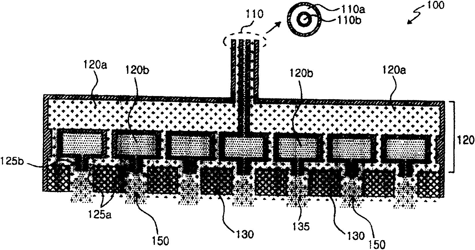
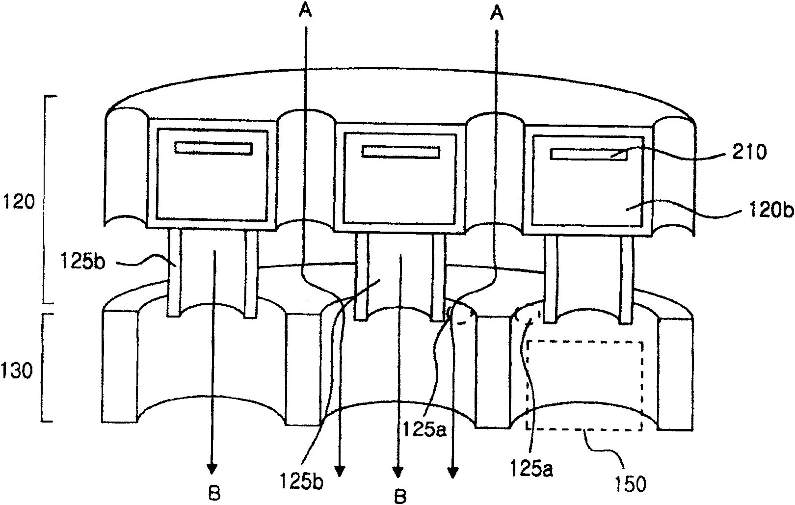
[0022] figure 1 A gas separation type shower head used in the present invention is shown. figure 1 The illustrated gas separation type showerhead 100 includes a gas supply module 110 , a gas separation module 120 and a gas injection module 130 .

[0023] The gas supply module 110 includes an outer supply pipe 110a and an inner supply pipe 110b separated from each other. The first precursor A is supplied to the outer supply tube 110a, while the second precursor B is supplied to the inner supply tube 110b.

[0024] The gas separation module 120 includes a first dispersion area 120a connected to the outer supply pipe 110a and a second dispersion area 120b connected to the inner supply pipe 110b. refer to figure 1 , the first precursor A is supplied to the outer supply pipe 110a and dispersed in the first dispersion area 120a, and the second p...


PUM


Abstract

An atomic layer deposition (ALD) apparatus using a gas separation type showerhead is provided. Accordingly, the ALD apparatus that employs the gas separation type showerhead including a gas supply module, a gas separation module, and a gas injection module. The ALD apparatus includes: a first precursor source storing the first precursor, which is connected to the outer supply tube; a second precursor source storing the second precursor, which is connected to the inner supply tube; a purge gas source storing a purge gas, which is connected to the outer and inner supply tubes; a power source which applies power for ionization to the gas separation module; and an exhaust unit which exhausts remaining materials of the reaction chamber.

Description

[0001] Background of the invention technical field [0002] The invention relates to an atomic layer deposition (ALD) process, and more particularly to an atomic layer deposition device using a gas separation type shower head. Background technique [0003] The ALD process is a process for depositing a semiconductor film with a thickness of less than 90 nm to form a film with a uniform thickness while suppressing impurities to the greatest extent. In a general ALD process, a cycle in which one precursor is adsorbed and removed and another precursor is also adsorbed and removed is repeatedly performed. [0004] However, in a conventional ALD apparatus, since the precursors are finally injected through different injection holes, the change of the gas flow causes the uniformity in the process conditions to be disturbed. Reaction time increased. [0005] On the other hand, since the reactivity between the reaction gas and the deposition gas must be greater at the relatively lo...

Claims


Application Information

Patent Timeline
IPC IPC(8): C23C16/513H01L21/02
CPCC23C16/45525C23C16/45544C23C16/45563C23C16/45574C23C16/52
Inventor 裵根鹤金京洙金昊植
Owner WONIK IPS CO LTD
Learn More