
Transmission device for small-sized vehicle

A transmission and fluid transmission technology, applied in transmissions, fluid transmissions, belts/chains/gears, etc., to achieve the effects of stable working characteristics, improved engine braking performance, and reduced shaking

Inactive Publication Date: 2010-02-24
HONDA MOTOR CO LTD
View PDF6 Cites 0 Cited by
  • Summary
  • Abstract
  • Description
  • Claims
  • Application Information

AI Technical Summary

Problems solved by technology

However, this fluid transmission device is a form with a lock-up clutch between the pump blade and the turbine blade. The friction clutch plate of the clutch on the outer periphery rotates together with the turbine shaft even when the engine brake is operating, and the turbine blades and pump blades with complex structures are also the remaining problems of the above-mentioned fluid transmission device.

Method used


Image

  • Transmission device for small-sized vehicle
  • Transmission device for small-sized vehicle
  • Transmission device for small-sized vehicle

Examples


Embodiment approach

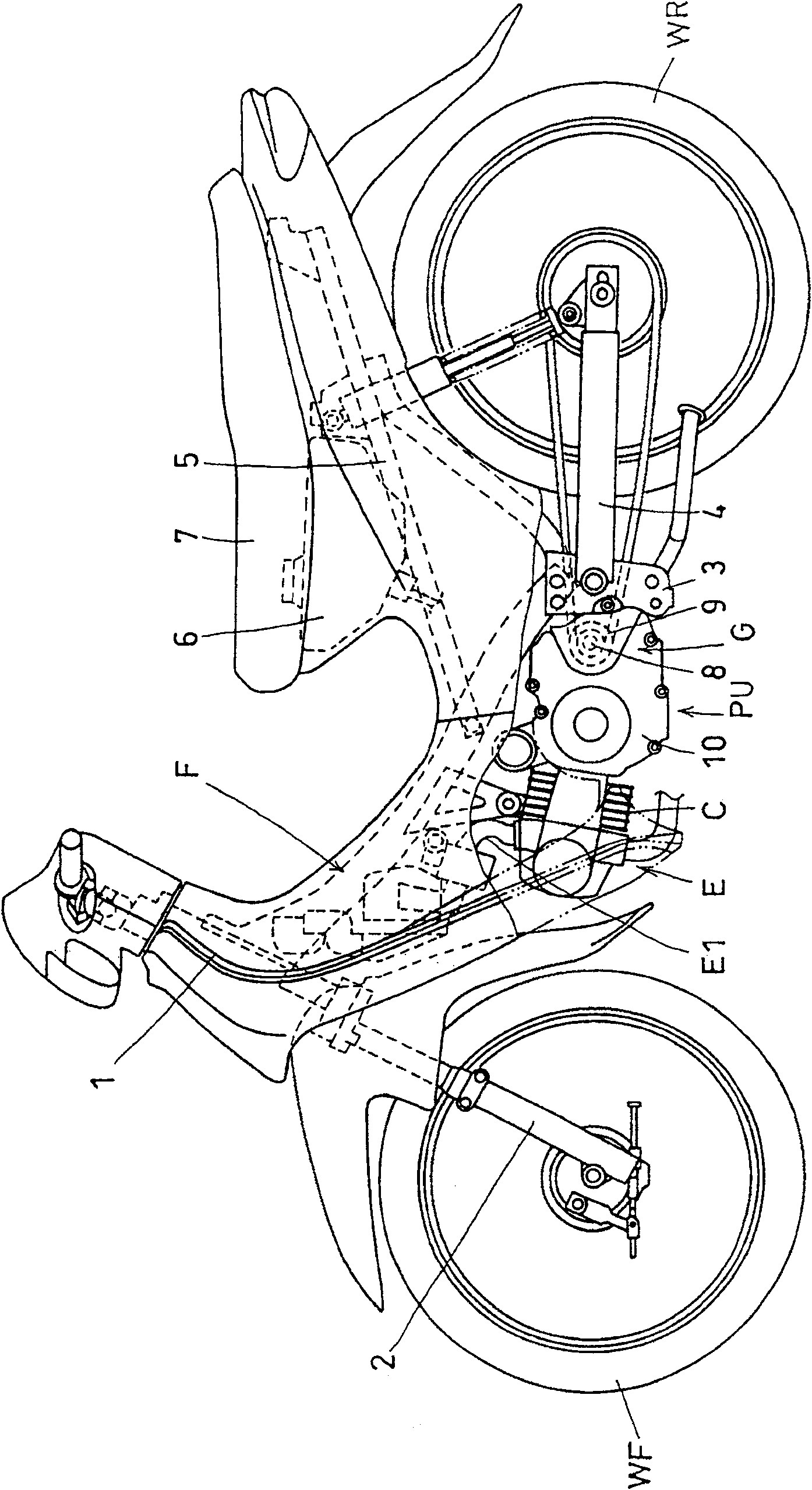
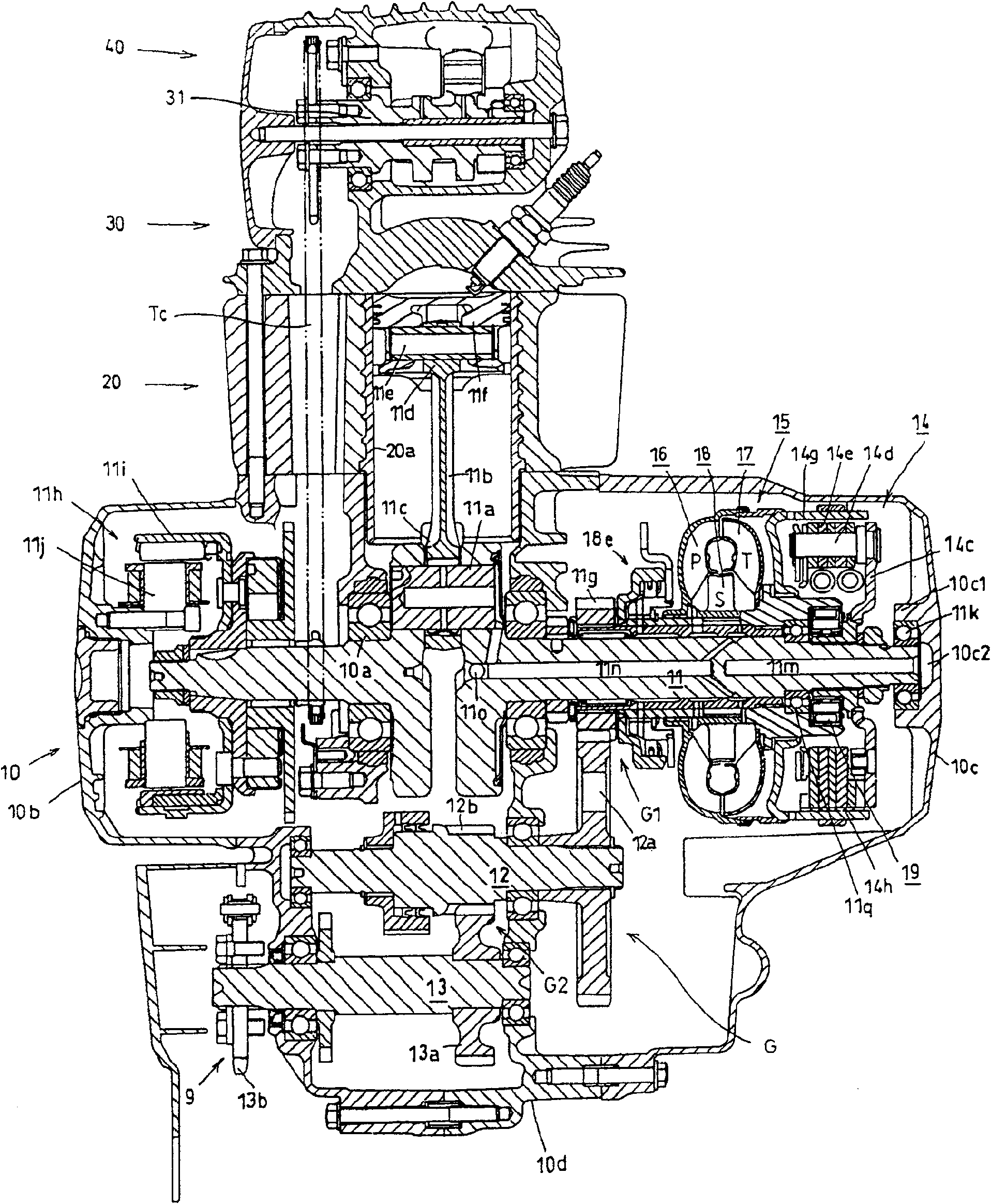
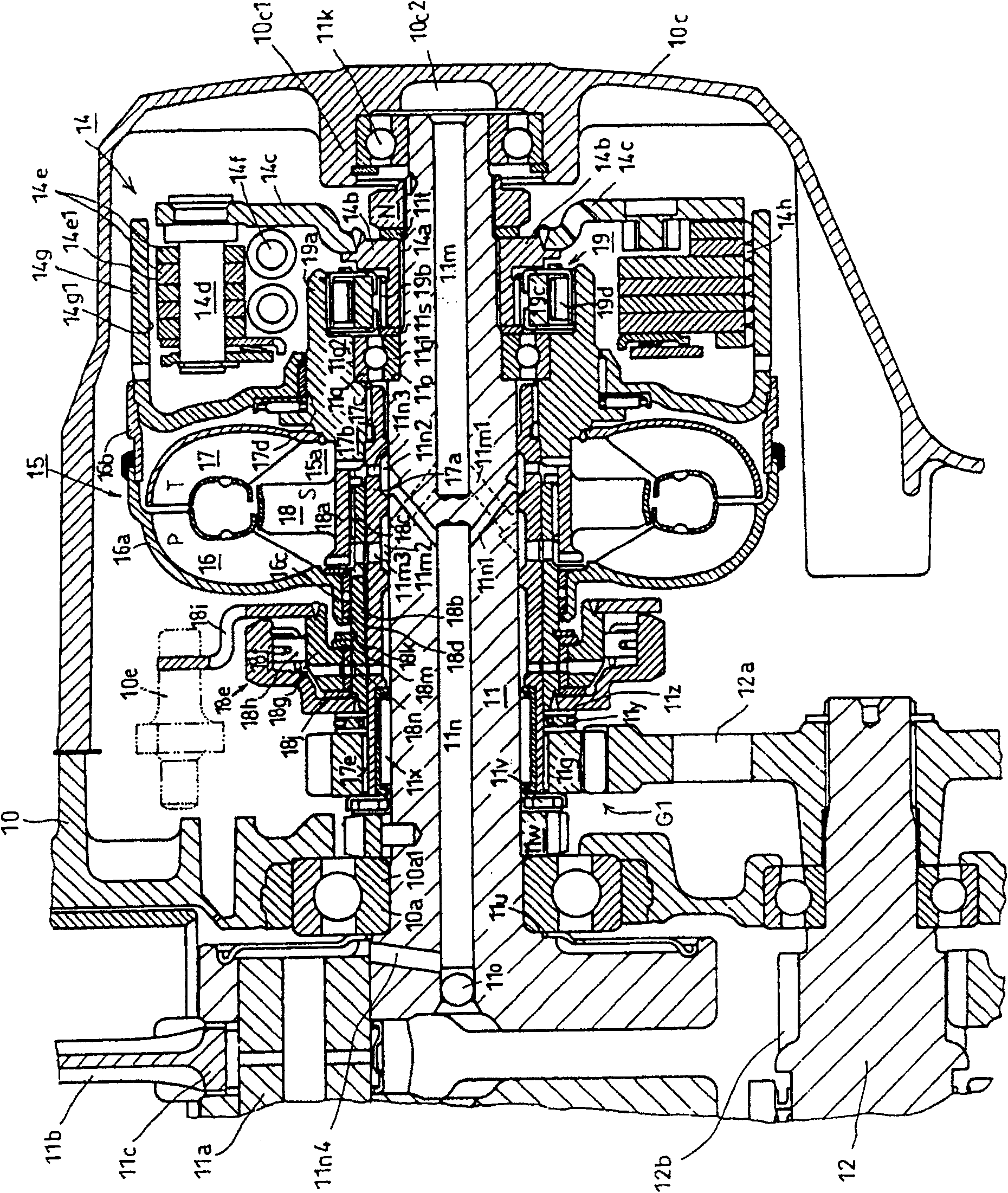
[0021] according to Figure 1 ~ Figure 3 Examples of the present invention will be described.

[0022] figure 1 A motorcycle equipped with a power unit PU including an internal combustion engine E and a speed reducer G according to this embodiment is shown in a side view. in addition, figure 2 shows a longitudinal sectional view of the power unit PU, and, image 3 express figure 2 An enlarged view of the main part.

[0023] refer to figure 1 , the motorcycle body frame F has a head pipe 1 at its front end, and the front fork 2 is supported on the head pipe 1 so as to be steerable, and the front fork 2 pivotally supports the front wheel WF. The middle part has a pivot plate 3 on which the front part of the rocker arm 4 is supported so as to be able to swing up and down. A fuel tank 6 and a passenger seat 7 covering the fuel tank 6 are supported on the outgoing seat beam 5 .

[0024] The power unit PU mounted on the vehicle, which is composed of the internal combusti...


PUM


Abstract

To ensure an effective engine brake function while simplifying the structure of a transmission mechanism by appropriately selecting the transmission mechanism for leading in engine brake force in a fluid transmission provided with a torque converter. The fluid transmission is provided with a centrifugal clutch 14 and the torque converter 15 arranged on a crankshaft 11, and the driving force of the crankshaft 11 is inputted to the torque converter 15 from the centrifugal clutch 14 and transmitted to a reduction gear G1 through a turbine shaft 17a of the torque converter 15 and further transmitted to driving wheels. Engine brake force is transmitted from the reduction gear G1 to a turbine hub 17b which is a clutch outer 19a of a one-way clutch 19 via the turbine shaft 17a and further to thecrankshaft 11 from a clutch inner 19b of the clutch 19.

Description

technical field [0001] The present invention relates to an improvement technology of a small vehicle fluid transmission device equipped with a torque converter. Background technique [0002] As a fluid transmission device for small vehicles, there is known a structure in which a speed change clutch and a torque converter as a fluid transmission device are connected in series with each other on the mechanism and arranged side by side on the crankshaft of an internal combustion engine, one of them is connected to the crankshaft, and the other is connected to the crankshaft. It is connected to the input shaft of the multi-stage transmission through the reduction gear. In addition, in such a conventional well-known fluid power transmission device, it is known that a lock-up clutch actuated via a turbine blade portion is provided with an engine braking force transmission function. In addition, differently, a structure is proposed in which the engine braking force is directly tra...

Claims


Application Information

Patent Timeline
Patent Type & Authority Patents(China)
IPC IPC(8): F16H47/06F16H41/24F16H45/00
CPCF16H2045/002
Inventor 泽村吉信山本敏弘熊谷吉彦木原照雄椿野幸博
Owner HONDA MOTOR CO LTD
Learn More