Al technical title is built by PatSnap Al team. It summarizes the technical point description of the patent document.
A pay-off device and cable technology, which is applied in overhead lines/cable equipment, transportation and packaging, and delivery of filamentous materials, etc., can solve the problems of easily damaged insulation and protective layers of cables, inconvenient installation and use, and loose and disordered cables. , to reduce labor intensity and prevent damage
Inactive Publication Date: 2018-09-28
江苏仟略信息技术有限公司
View PDF0 Cites 14 Cited by
Summary
Abstract
Description
Claims
Application Information
AI Technical Summary
This helps you quickly interpret patents by identifying the three key elements:
Problems solved by technology
Method used
Benefits of technology
Problems solved by technology
However, for some thicker cables, there will be a certain bending deformation when they are pulled out from the surface of the pay-off roller, which is not easy to install and use. When relying on large pliers or other tools to straighten, it is easy to damage the insulation protection layer of the cable, and put it on the wire. After the line is finished, the pay-off roller continues to rotate under the action of inertia, pushing the remaining cables on the reel forward or making the originally tight cables on the surface of the pay-off roller fluffy and disordered
Method used
Image
Click on the blue label to locate the original text in one second.
Reading with bidirectional positioning of images and text.
Examples
Embodiment Construction
[0017] The following will clearly and completely describe the technical solutions in the embodiments of the present invention with reference to the accompanying drawings in the embodiments of the present invention. Obviously, the described embodiments are only some, not all, embodiments of the present invention. Based on the embodiments of the present invention, all other embodiments obtained by persons of ordinary skill in the art without making creative efforts belong to the protection scope of the present invention.
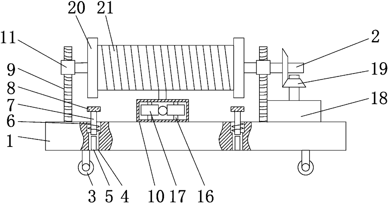
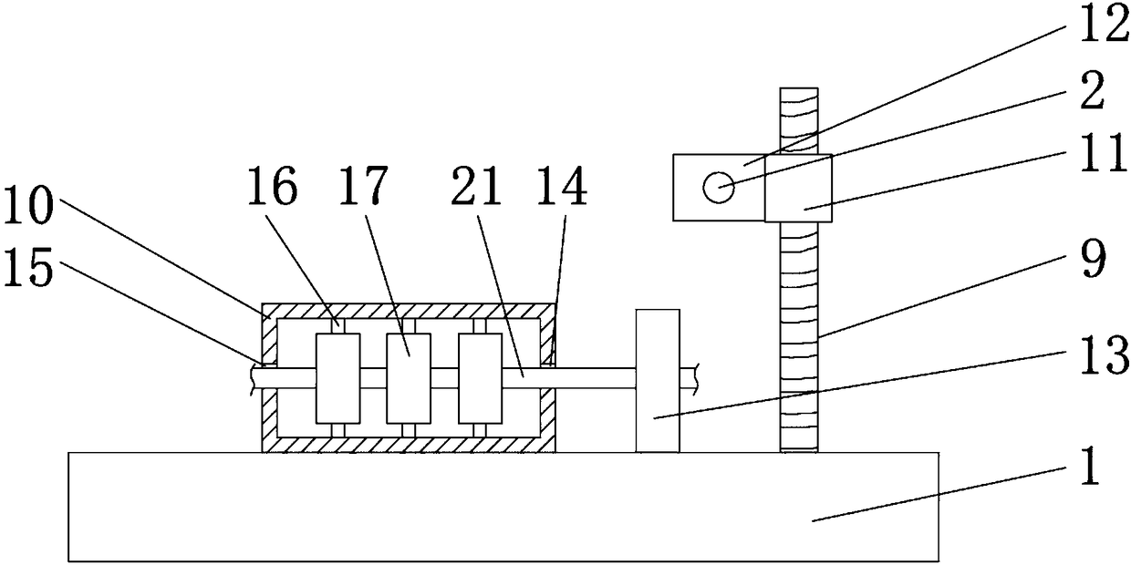
[0018] see Figure 1-2 As shown, a cable pay-off device includes a base 1 and a first rotating shaft 2, a pulley 3 is installed at the bottom of the base 1 to facilitate the movement of the device; the surface of the base 1 has a groove 4; the groove 4 An electromagnet 5 is installed at the bottom; the inner wall of the groove 4 is elastically connected with an iron bar 7 by a spring 6; the top of the iron bar 7 is fixedly connected with a friction plate 8, wh...
PUM
Abstract
The invention discloses a cable paying-off device. The cable paying-off device comprises a base, a first rotating shaft, a pulley, a groove, an electromagnet, a spring, an iron bar, a friction piece,a ball screw, a straightening box, a ball nut, a connecting plate, a traction ring, a cable inlet hole, a cable outlet hole, a second rotating shaft, a pressing wheel, a motor, a bevel gear, a paying-off roller and a cable. The cable paying-off device has the beneficial effects that by arranging the electromagnet and the iron bar, when the cable paying-off device stops operating, the friction piece at the top of the iron bar is in friction with the surface of the paying-off roller in time, so that the paying-off roller is braked, and inertial rotation of the cable paying-off roller after paying-off of the cable paying-off roller is stopped is prevented; by arranging the straightening box, the cable is effectively extruded under the action of the pressing wheel, so that the bent and deformed cable recovers to be a straight line, and an insulation protective layer is effectively prevented from damage; and by arranging the ball screw, workers can easily mount the paying-off roller on thecable paying-off device, and the labor intensity of the workers is reduced.
Description
technical field [0001] The invention relates to a pay-off device, in particular to a cable pay-off device, which belongs to the technical field of electric power communication equipment. Background technique [0002] With the rapid development of social economy and the modernization of cities, the demand for communication of various enterprises, institutions and residents is also increasing rapidly, and the erection of electric communication is becoming more and more common. It is an important auxiliary equipment for the construction of electric communication structures. [0003] The cable is usually coiled on the surface of the pay-off roller. When carrying out electric power construction, the cable is released from the surface of the pay-off roller by a pay-off frame or a pay-off vehicle. However, for some thicker cables, there will be a certain bending deformation when they are pulled out from the surface of the pay-off roller, which is not easy to install and use. When ...
Claims
Application Information
Patent Timeline
Application Date:The date an application was filed.
Publication Date:The date a patent or application was officially published.
First Publication Date:The earliest publication date of a patent with the same application number.
Issue Date:Publication date of the patent grant document.
PCT Entry Date:The Entry date of PCT National Phase.
Estimated Expiry Date:The statutory expiry date of a patent right according to the Patent Law, and it is the longest term of protection that the patent right can achieve without the termination of the patent right due to other reasons(Term extension factor has been taken into account ).
Invalid Date:Actual expiry date is based on effective date or publication date of legal transaction data of invalid patent.