
Piezoelectric ceramic fibre containing metal core of partly painted electrode

A piezoelectric fiber, metal core technology, applied in piezoelectric devices/electrostrictive devices, piezoelectric/electrostrictive/magnetostrictive devices, circuits, etc. and other problems to achieve the effect of overcoming application defects

Active Publication Date: 2010-02-24
NANJING UNIV OF AERONAUTICS & ASTRONAUTICS
View PDF3 Cites 2 Cited by
  • Summary
  • Abstract
  • Description
  • Claims
  • Application Information

AI Technical Summary

Problems solved by technology

The surface of the existing fiber is all plated with electrode materials, and the parameters in the stretching mode can only be measured along the length direction, that is to say, it can only realize the stretching vibration in the length direction, and cannot realize the bending vibration, which limits its use as a driving force. Component application range

Method used


Image

  • Piezoelectric ceramic fibre containing metal core of partly painted electrode
  • Piezoelectric ceramic fibre containing metal core of partly painted electrode
  • Piezoelectric ceramic fibre containing metal core of partly painted electrode

Examples


Embodiment 1

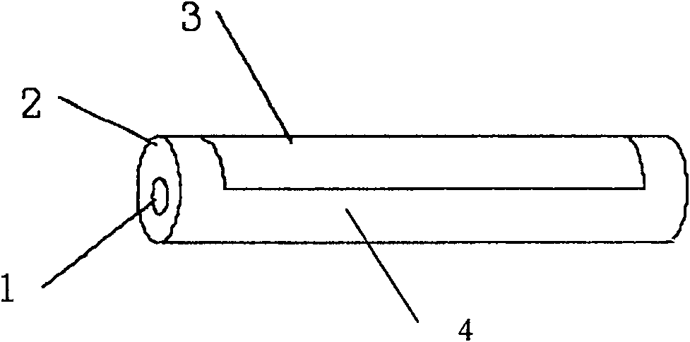
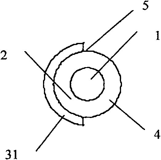
[0021] Embodiment one: if figure 1 , figure 2 As shown, the piezoelectric fiber containing a metal core of the partially coated electrode of this embodiment includes a metal core 1, a piezoelectric material 2 coated on the metal core 1, and a coated electrode 3 coated on the outer surface of the piezoelectric material 2 , the surface of the piezoelectric material 2 includes a coated electrode portion 3 and an uncoated electrode portion 4, the coated electrode portion 3 is a coated electrode 31, which partially covers the piezoelectric material 2 along the direction in which the piezoelectric fiber containing the metal core extends The surface; Wherein, coating electrode part 3 occupies half of the surface area of ​​piezoelectric material 2;

[0022] The diameter of the metal core 1 is 25 microns, and the material of the metal core 1 is platinum;

[0023] The section of the piezoelectric fiber containing the metal core of the partially coated electrode of this embodiment is ...

Embodiment 2

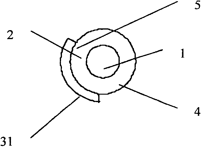
[0029] Such as figure 1 , image 3 As shown, the piezoelectric fiber containing a metal core of the partially coated electrode of this embodiment includes a metal core 1, a piezoelectric material 2 coated on the metal core 1, and a coated electrode 3 coated on the outer surface of the piezoelectric material 2 , the surface of the piezoelectric material 2 includes a coated electrode portion 3 and an uncoated electrode portion 4, the coated electrode portion 3 is a coated electrode 31, which partially covers the piezoelectric material 2 along the direction in which the piezoelectric fiber containing the metal core extends The surface; Wherein, the coated electrode part 3 occupies one-third of the surface area of ​​the piezoelectric material 2;

[0030] The piezoelectric fiber containing the metal core of the partially coated electrode in this embodiment, the diameter of the metal core 1 is 10200 microns, and the metal core 1 is made of a high temperature resistant material, suc...


PUM

PropertyMeasurementUnit
diameteraaaaaaaaaa
diameteraaaaaaaaaa

Abstract

The invention relates to a piezoelectric fiber containing a metal core with part coated with an electrode, which comprises a metal core (1), a piezoelectric material (2) coating the metal core (1) anda coating electrode (3) coating the outer surface of the piezoelectric material (2). The surface of the piezoelectric material (2) comprises an electrode coated part (3) and a non electrode coated part (4); the electrode coated part (3) is a coated electrode (31) which partially covers the surface of the piezoelectric material (2) along the extending direction of the piezoelectric fiber containing a metal core. The piezoelectric fiber containing a metal core with part coated with electrode of the invention can realize the driving functions of driving components such as traditional piezoelectric bimorphs, can be used as micro-drivers and for energy recycling and vibration control, and especially can realize the function of bending vibration, thus overcoming the application disadvantages ofthe existing piezoelectric fibers.

Description

1. Technical field [0001] The invention relates to a piezoelectric fiber, in particular to a piezoelectric fiber containing a metal core. 2. Background technology [0002] Most smart structures adopt the structural form of integrating functional devices and matrix structures. In order to facilitate integration with the structural matrix, this puts forward new requirements for the geometric shape and size of functional components in smart structures. Traditional piezoelectric functional devices are mostly in the form of blocks and sheets. Due to their large volume, they are not easy to integrate with the matrix structure. When embedded in the matrix structure, it will have a great impact on the strength and reliability of the structure, and will also change many properties of the structure. , and even affect the use of the structure and shorten the service life of the structure. Ideal geometries to meet the ease of integration requirements imposed by smart structures are thi...

Claims


Application Information

Patent Timeline
Patent Type & Authority Patents(China)
IPC IPC(8): H01L41/09H01L41/047
Inventor 裘进浩朱孔军边义祥季宏丽
Owner NANJING UNIV OF AERONAUTICS & ASTRONAUTICS
Learn More